Lithium Battery Boost Power Supply Comparison

I purchased two boost converters or DC to DC power supplies, or whatever else people want to call them on eBay. One was a LiPower board from Sparkfun for $14.95. I assume it’s made in the US, has a battery connector and can be soldered with 0.1in pitch terminals. It’s setup for low voltage drop out at 2.6V but there is a small hack to reduce that (though I feel like you have better options if you’re trying two NiMH batteries because it has reduced current abilities from the hack.) See the sparkfun site for more details, including the link to the hardware hack. The output is a small solder jumper that comes preset to 5V but wouldn’t take but a minute to convert to 3.3V.  https://www.sparkfun.com/products/10255

I put a small load (my anticipated load of a project) of 50mA and this device measured at 85.3% efficient.

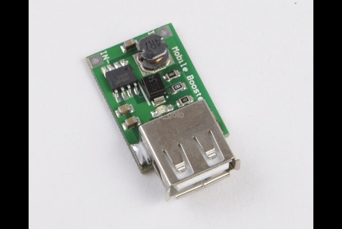
The other device I bought was a cheap-o Chinese converter that came as a two-pack from Hong Kong. It came with a USB connector and took anything 2 to 5V. I tested this with a 2.4V battery pack and it seems to cut out at just under 2V. The efficiency was measured at 77.0%… Also with a 50mA load. My input voltage was a bench power supply set to 3.7V to simulate a LiPo battery on both tests. A nicety of the Chinese “mobile booster” board was the red LED showing output power status. The LED blinks rapidly when it goes into low voltage cutout. The cheap-o board also output 5.20v which was fine for my application. I think I gave roughly $4 both boards with free shipping.

20130731-215222.jpg

20130731-215231.jpg

Cheap 5V power from that 3.7V LiPo

I currently have all projects on hold while I join a BMP085 break out board from SparkFun with a 8pin PIC into a barometer for my upcoming section hike of the PCT in September (I’m fairly certain I wouldn’t have a job nor wife if I declared I was going to through-hike). This year I’m carrying a DeLorme InReach SE stand alone two way satellite communicator so my wife can track me and send the occasional text message. They declare 100 hours of run time but my tests show that 72 hours is average. This isn’t going to cut it…I’ll likely need 1 full recharge to get me through (via USB cable). This led to my decision that the barometer is getting a larger LiPo battery and I am adding a boost converter… In my rush to get anything finished and somewhat tested I sniffed around eBay and found these 2-5V to 5V boost converters (with USB connector) at a ridiculously low price of 2.50$… It’s obviously coming from China. What a great way to spend some eBay bucks?! I can check that one off assuming these aren’t total garbage. I bought two and they claim 87% efficiency at 3.7V. I’ll check them out and post my results. Now I have to decide if I’m going to Bluetooth data to an android device or if I’ll throw an LCD on my project…I think weight will determine my choice.

20130722-094145.jpg

PIC-based ESR meter

My homebrew ESR meter spots a cap that is less than desirable. If anyone is interested I have my .asm code I am happy to share. The board is an Olimex prototyping development kit I got from ‘microcontrollershop’. It’s all assembler .. No C version and no desire to work on this anymore. The electrical aspects are documented in the code to some degree (enough that *I* could rebuild it…) I don’t have any plans for a kit. If you want the code you’ll have to agree that you’re building this project for yourself with no re-distribution. I don’t trust my code enough to be considered for some sort of commercial use.

20130715-082931.jpg

IGBT Pack and Drive Pin Diagram

So if anyone runs into an IGBT pack from a York Chiller I’ll do you a solid and give you a pin diagram.

York part number: 031-02061-001

The connector is of this style (p/n from package, I forget which side): 1-794223-0 http://www.digikey.com P/N: A100435CT-ND .. using this you can find both pieces.

.. all TTL is 5V the “/” is a low level input designator. PIN

1: U1 (5VDC)

2: U1+U2 /FAULT

3: U4

4: U5

5: U5+U6 /FAULT

6. T1 (RTD 5K)

7. DC NEG

8. Vcc (5VDC)

9. Isolated Power (I think this is 24VAC but I’m not sure)

10. U2

11. U3

12. U3+U4 /FAULT

13. U6

14. /RESET

15. T2 (RTD)

16. N/C

17. DC NEG

18. Other side of isolated input I believe.. I blew mine up before I could fully test this.

… as for the IGBT it’s 2, 4, 6 are + (up to 1.2kV) and 1, 3, 5 are the negative side, the others are the 3 phase output. New, this pack is painfully expensive.. $1,400 but maybe you’ll run into a good deal or some “garbage” as I did. Good luck!

Killed my IGBT pack & driver

20130623-164618.jpg

What a rookie mistake… My variac is grounded… I’ve gotten too spoiled by working on a lot of isolated 24VAC circuits lately… One little check with the scope and boom. PCB death… So much for my one-of-kind short cut. I suppose I need to invest in one of those sets of isolated probes. Silver lining is I didn’t let the smoke out of the front-end of my tektronix scope.

IGBT EconoPACK test for my homebrew variable frequency drive.

I mocked-up a test of my IGBT Infineon EconoPACK. I had a 24VDC to 95VDC 200w boost brick and fed the IGBT that just because… It made a nice isolated power supply. After I got everything together I feared I had gotten a bad module, but because I know myself I went over everything and realized I failed to pull the /RESET up and so I figure that’s my most likely cause of my inability to get this thing to switch. Everything on the board looks good.. I guess I’ll give it a try again tomorrow. I just got my Pi booted up but I’m hoping I can easily jump in and use it to drive this IGBT pack. If not I’ll just fall back to a PIC. Driving the pack is straight forward; I was just hoping to save myself some development time. This will be my first VFD.. I’m hoping not my last. I scored a 230V 3 phase motor that is about 2 HP. I’m about 95% sure of what I’m going to use this for but I’ll admit it wouldn’t be the first time I stole parts from one project to build another. I’ll see what this Pi can do this weekend after I get back from taking a hike with my daughter on Saturday. I guess Monte Cristo is getting shut down for two years and I want her to experience it. Eight miles is the limit to her hiking abilities right now but she’ll make it, 700ft of elevation gain.. she probably worked harder walking around disney land.

I pulled most of the parts of this project out of storage. While going through old parts I brought back from my house in SD I also found some nifty scintillation detection goodies, gobs of tools, some of my CDP1802 Elf II stuff and a ton of other stuff that I’m sure will make it’s way to my blog. I found a few boxes of 2-20GHz  stuff I was ratting away for some EME project but I think I’ll just give that away to a HAM radio club.

My first attempt at testing the IGBT EconoPACK.. this one is oversized but the price was right. 1.2kV 450A... yeah... way over sized.
My first attempt at testing the IGBT EconoPACK.. this one is oversized but the price was right. 1.2kV 450A… yeah… way over sized.

Variable Frequency Drive Shortcut

I’ve had a project sitting on the back burner for quite a lot of time, really an embarrassing amount of time. It’s been a good 3 or 4 years since I started a yet unfinished variable frequency (speed) drive. I plan to drive a 3 phase AC motor for another project later to be reviled. I’ve had some trials both successful and magnificent failures but I decided to skip that whole learning to build a proper motor drive set when I came across a user York chiller compressor driver. The pin out wasn’t difficult to reverse engineer and went even more quick as I had a basic schematic of the interconnections of the York boards on a PDF I found online. Shown in the photo is the drive board. This is about 80% of my work taken care of for me all for the low price of a few bucks. I don’t know if you’ll be able to find yourself a drive board I just got lucky. I suspect if you can find an old used variable frequency drive you can just borrow it’s guts. If you like this board perhaps you can search by part number. It’s the 031- number found in the middle of the PCB. The connector was found through @digikey :

A25718-ND    CONN PLUG 18POS MINI UNIV-MATE
A33338-ND    CONN HDR 18POS STR DUAL .163 TIN
A100434CT-ND    CONN PIN 16-20AWG MINI-U M-N-L2
A100435CT-ND    CONN SCKT 16-20AWG MINI-U M-N-L2

I ordered both sides of the connector for testing and my own interface board. Note: I haven’t received this parts so I haven’t absolutely verified these are correct but the pin keys and measurements against specifications appeared correct.


VFD IGBT and driver board.

I realize I could have used “XYZ development kit”, and I could have also dedicated more time to this project but my time is worth something and I have a chronic issue with being cheap.

Update: DIY Electric Boiler Installation

On my visit to the ‘Acres I got my electric boiler hooked up. It worked really well at 140 deg F. I didn’t have a great load and next visit I’ll push it up to 180 deg where I’ll get a lot better heat transfer out of the radiators. No real hitches other than the TACO electronic low water cut off is a lot more sensitive that I’d like. On initial start-up I had to power cycle it to get it out of “service required” mode.. It’s also very sensitive to air pockets but it resets automatically.

Update: Electric Boiler installed. It worked well in testing, unfortunately the weather was unseasonably warm so I couldn't give it a really good load for testing besides the start-up from ~60 deg F loop water temperature.
Update: Electric Boiler installed. It worked well in testing, unfortunately the weather was unseasonably warm so I couldn’t give it a really good load for testing besides the start-up from ~60 deg F loop water temperature.

Advanced PCB Etching Tank Control

I’ve consistently had inconsistent results from etching PCBs. My best luck has been with PCB developing using a laser printer and transparency sheets. I was whiping up a batch of PCBs for my 6 meter amplifier when I decided I was really getting annoyed with figuring  out how to keep the etchant hot, but not too hot. This PLC modulates the temperature at a predefined setpoint. It switches a relay on and off to a heating element I scrapped out of a 10$ coffee maker and I used a little fountain water pump that cost me $8. The rest of the materials I had laying around. I kept my etchant at 125 deg F. A probe within the 5 gallon bucket monitored the temperature. Because of the staged heating the temperature varied about 5 degrees total. The heat of the water pumping transferred through the plastic container and heated the etchant so I didn’t have to directly heat the etchant.

I still have the bones of this project though I haven’t etched a board in a solid two years so I re-purposed some of the items.

Controls Cabinet
Controls Cabinet
MG Chemicals PCB enchant container with the 5gal bucket that is filled with heater water.
The hole system... the laptop isn't needed I just had it hooked up to "tune the PID loop".
The whole system… the laptop isn’t needed I just had it hooked up to “tune the PID loop”.
I heat the water by circulating water through this coffee maker heater.
the display panel, pretty simple but gets the job done.