I’ve returned from vacation and brought back a ton of tidbits to share over the next few weeks.
I left the beautiful Pacific Northwest to work on my ranch house in Meade County, South Dakota. I had a number of projects I hoped to complete while there and got through a fair portion of my list that was mostly filled with “wishful thinking” mini-projects. Not all of these are electronics based but bear with me, there are some items of interest.. no guarantee it’s you who is interested though 🙂 I also hit up an AM site with one of my best friends and scored some goodies!
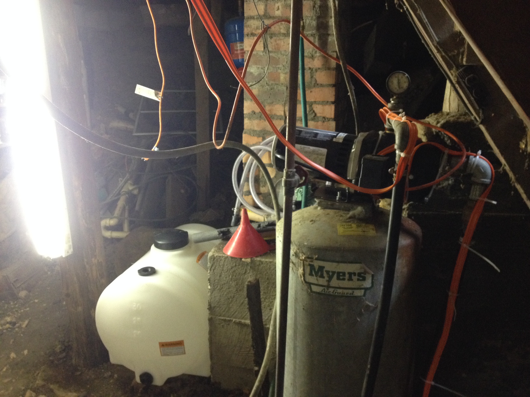
Water: My artesian well has low flow, this isn’t crippling but it can be a hassle. I’ve installed a water tank with a float that allows the well to fill a tank through a 3/4″ in-ground sprinkler solenoid. When pressure drops and the well booster pump kicks on it sucks every bit of water it can including any air it can find out of a contentiously flowing drain into a stock tank a couple hundred feet down the line. Now I’ll have a reservoir to provide extra water on the fly and filter some slight sand in the water supply.
Pump and Water Tank in the basement
Sewer: I had a collapsed sewer line… talk about the shits! 😀 I thought this was about all I would get done on my vacation as I was going to have to hand dig the line.. it was about 12 wide, 5 foot down. Luck day, I had a good friend stop by and helped me out a bit… that took off a few minutes of rockin’ the shovel.
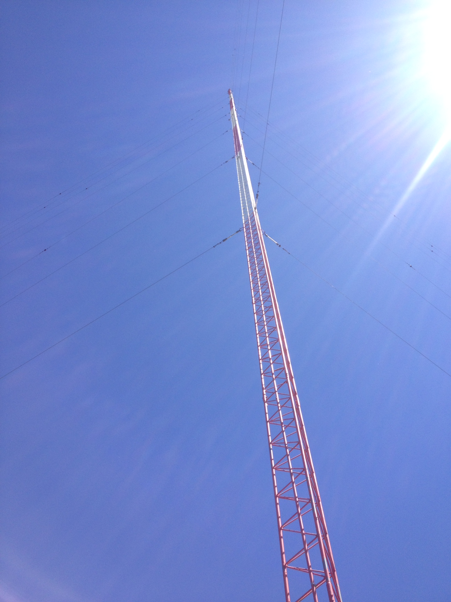
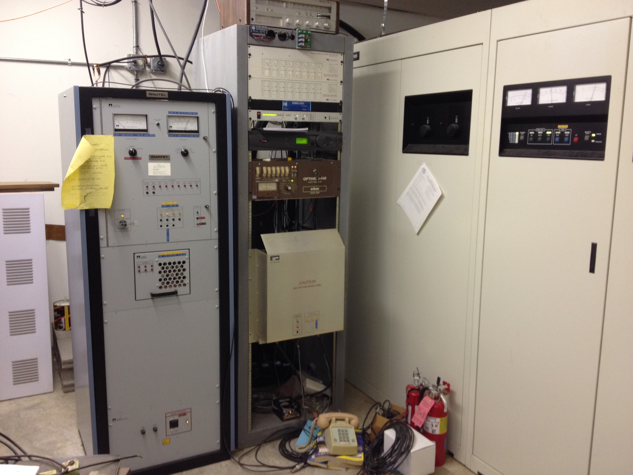
With all that work out of the way I had some time to meet up with a friend at an AM broadcast site while he was performing some maintenance. I used to apprentice under him but ended up going a different career route. Not sure I made the right choice some days?
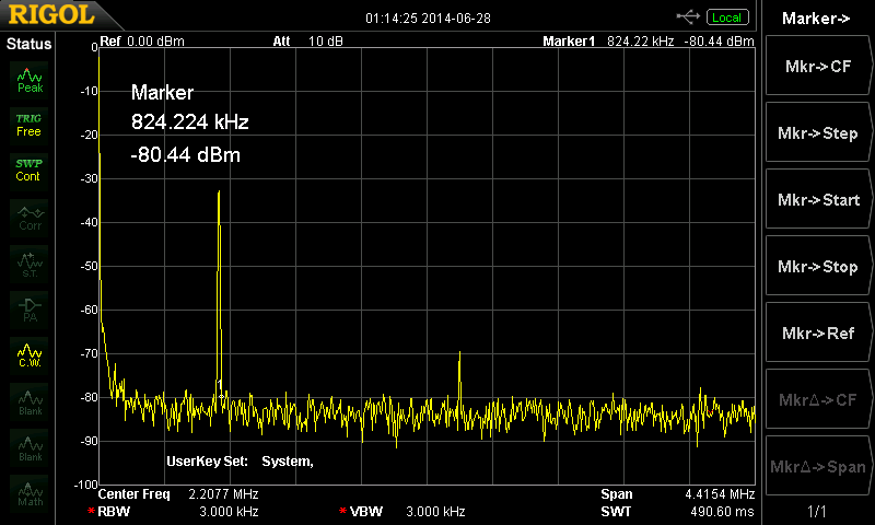
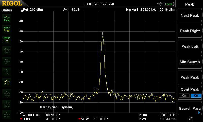
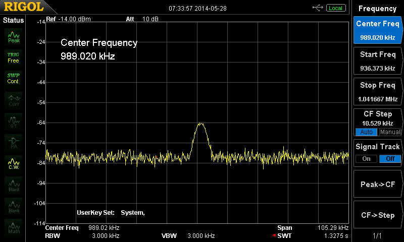
I grabbed my Rigol spectrum analyzer (you bring yours with you on vaca as well, right?) and threw a piece of wire into the input about a hundred feet away from the tower… the station is on 810KHz AM.
marker was obviously not on the peak on the reading above.
I took a ton of readings, compared mine to a much more expensive SA (very satisfied with the results) as well as taking some readings on a 948MHz STL transmitter.
I scored a nice directional sampling line and a bunch of SMA connectors with coax, a 20 watt digital OTA cable transmitter and a ton of other little goodies while I was at it. I great score. I got a VCXO, some filters, attenuators and just a ton of stuff I’ll check out here and there.
Finally, I’ve got some video to edit and drop on the YouTube channel as well but I’ll get to that in the coming days.
We did it, 0xEE.net is live. Our first post is a very detailed look into the PIC UART. This article is a stepping stone for other projects we have lined up. Tell us what you think!
In other bits I haven’t had a lot of time to do other things, I have been busy building two dev boards and write code for the above mentioned article but my Saturday was spent helping my sister and wife at their yard sale. It came away with a surprise for my daughter and an old Pelco dome camera. Video is a lot more interesting to look at on a scope than it is on an SA.
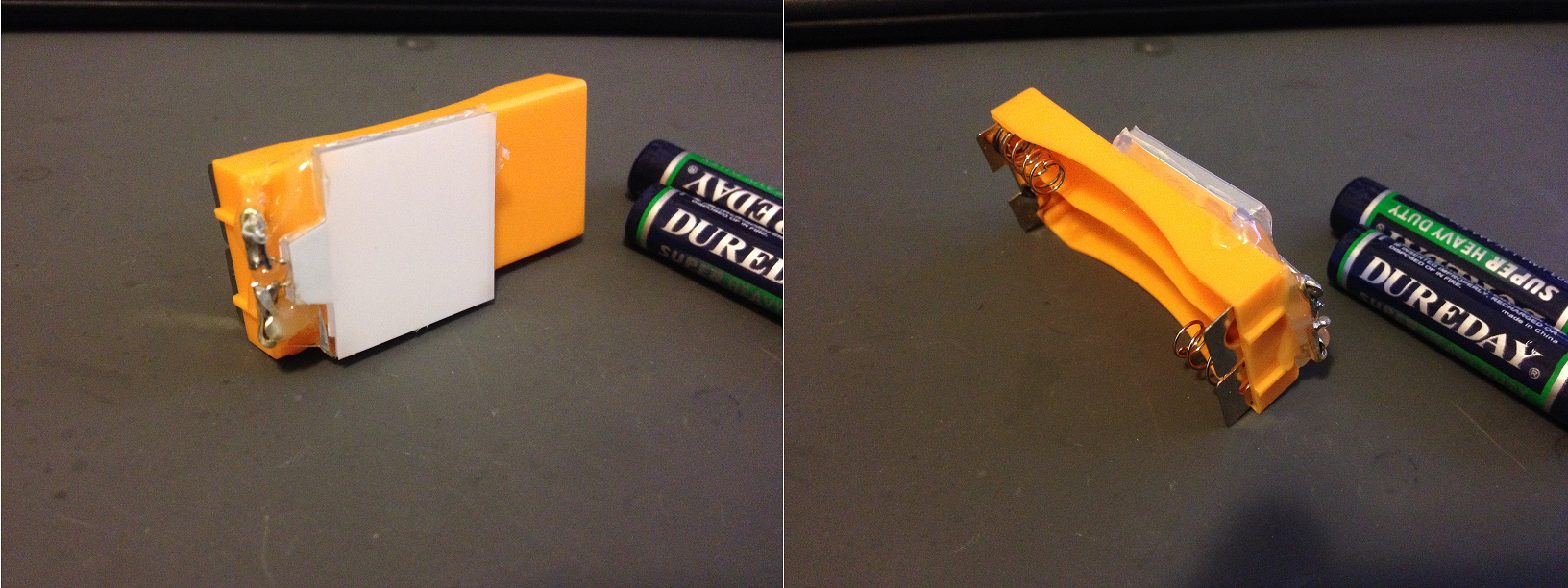
I also hacked up a super simple camping nightlight for my daughter. We are going camping the weekend after father’s day. I tore a cheap-o handheld temperature gun apart to get the thermopile and had a bunch of spare parts. The battery case and backlighting for the LCD will make a nice nightlight. No switch but she kills the batteries anyways as her flashlights never get shut off. I’ll have to grab some rechargeables..
I hope you all have a pleasant memorial day weekend. I thank all my fallen military service family, and their families for their service and their sacrifice.
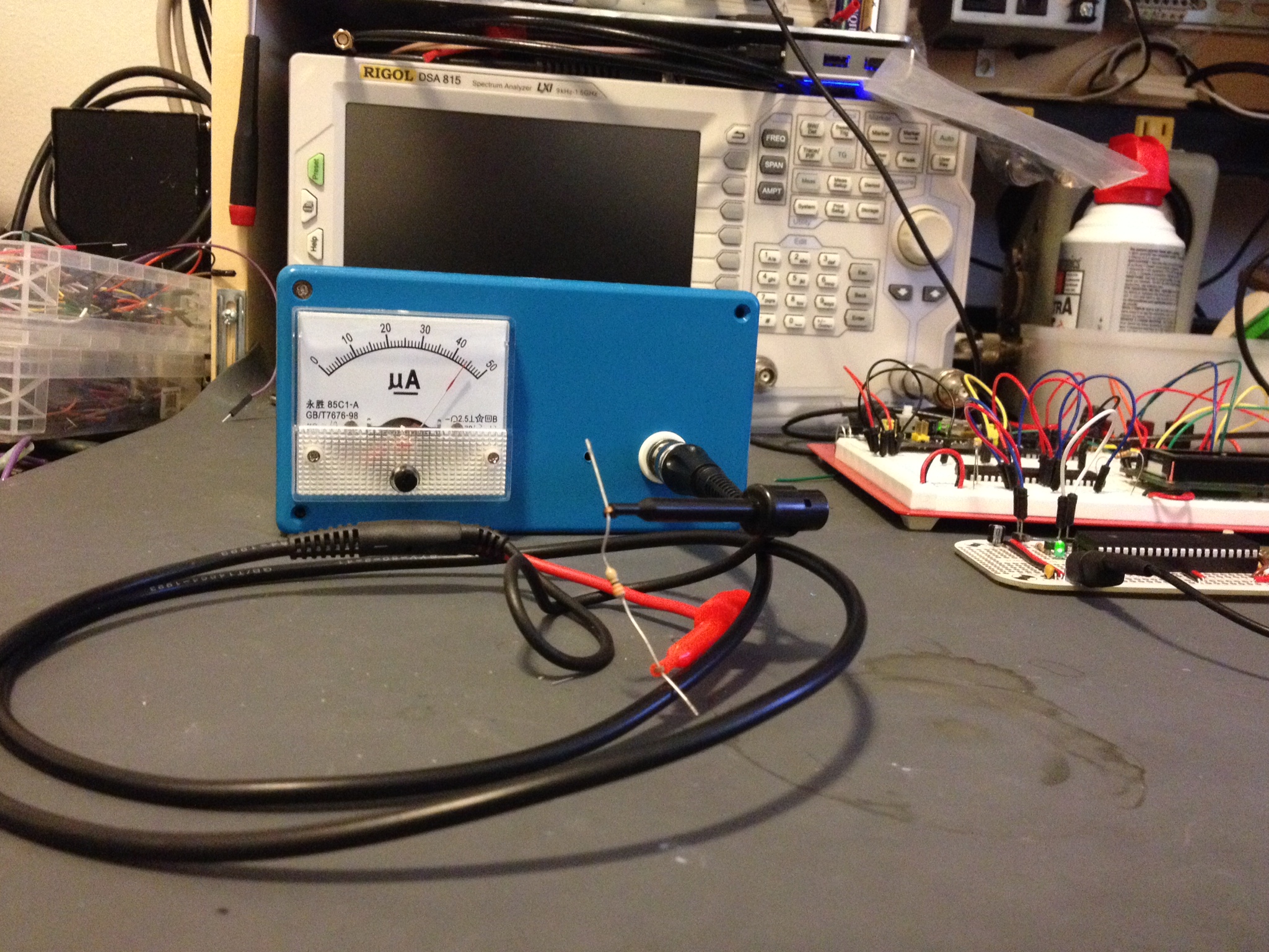
In the Sept – Oct 13 ARRL publication of QEX, W0PCE has a nice article on ESR (Equivalent Series Resistance) meters. I won’t go into details because I did on a blog post I have saved in drafts for when I finish my own ESR meter but the one sentence version; An ESR meter tests electrolytic capacitors. This meter is a nice analog ESR meter that works well if you are just looking for a good/no-good meter reading.
A friend of mine when in on a buy from FAR circuits to get the board. I believe I reviewed this earlier? If not it’s in my ESR post.. so that’ll come. The board was dirt cheap but if you’re particular you might be better off using protoboard. I don’t know where they got the parts package, but it all worked and came with everything except the connector, meter and battery pack.
Shown is a 33 Ohm resistor for testing to see that 33 Ohms is nearly-full scale which is about perfect for me. I went with a BNC connector and cable… just because I have a ton of them. It’ll be hard to finish my updated ESR meter now that I have this but I’ll find the inspiration some time. 😀
I’m working on a GPS-based WWVB simulator and I’m pretty close to finished. I wanted to share up to the point where I add on the WWVB circuits and have it stripped down to just the PIC development board and GPS module.
This is on a Mikrelektronika PIC Clicker 18F47J53 development board and a QUECTEL L30 “GPS2” Click board (Mikroe’s module boards built for MikroeBus).
The code is below, I’ll leave the rest of the explanation in the video.
NMEA stream from this module
The good stuff..
/*

* File: main.c

* Author: Charles M Douvier

* Contact at: http://iradan.com / 0xEE.net / @chasxmd

* Created on April 4th, 2014

*

* Target Device: PIC Click / 18F47J53

*

* Project: Mikroe.com GPS2 test

* Using a PIC Click Dev board and GPS2 click module I am reading the NMEA

* string and declaring a "lock" by turning on the LED on RA1

*

*

* Version:

* 0.1 First build I could prove I had GPS lock

*

*

*

*/

#ifndef _XTAL_FREQ //blah blah not the right way I don't care

#define _XTAL_FREQ 8000000 //8Mhz FRC internal osc

#define __delay_us(x) _delay((unsigned long)((x)*(_XTAL_FREQ/4000000.0)))

#define __delay_ms(x) _delay((unsigned long)((x)*(_XTAL_FREQ/4000.0)))

#endif
#include
#include
#include
#include
//config bits
#pragma config OSC=INTOSC, WDTEN=OFF, CP0=OFF //Internal OSC, No WDT and No code protect
#pragma config IESO=OFF, FCMEN=OFF
#pragma config XINST = OFF
#pragma config PLLDIV = 1 //Divide by 1
#pragma config STVREN = ON //stack overflow/underflow reset enabled
#pragma config XINST = OFF //Extended instruction set disabled
#pragma config CPUDIV = OSC1 //No CPU system clock divide
#define _XTAL_FREQ 8000000 //defined for delay
char ctxt[120]; //buff NMEA string
volatile unsigned int ping, isrcall, index, reading, new_rx;
int ready, gpgga, gprmc; //gps associated vars
//char *rxdata;
//volatile unsigned int uart_data; // use ‘volatile’ qualifer as this is changed in ISR
/*
* Interrupt Service
*/
void interrupt ISR() {
if (PIR3bits.RC2IF) // see if interrupt caused by incoming data
{
isrcall = 0x01;
char temp;
temp = RCREG2; // read the incoming data
if(temp==’$’ && new_rx==0) //if first char of a GPS string..
{
index = 0; //reset index
reading = 1; //from now on go to else if
}
else if(reading == 1) //in middle of GPS sentence
{
ctxt[index] = temp; //load it up
index++; //increment index
ping = 1; //this is for debugging
if(index > 50) //thats more than enough data
{
index = 0; //reset index
reading = 0; //no longer storing the string
new_rx = 1; //”ding”
}
}
//PIR3bits.RC2IF = 0; // clear interrupt flag
}
//RCSTA2bits.FERR = 0; //Clear errors
//RCSTA2bits.OERR = 0;
}
/*
* Set up my ports
*/
void init_io(void) {
// This code before the TRIS setup is for switching the RX2/TX2 to proper pins for the dev board
INTCONbits.GIE = 0; //no interruptions please
EECON2 = 0x55;
EECON2 = 0xAA;
PPSCONbits.IOLOCK = 0; //turn off PPS write protect
TRISEbits.TRISE0 = 1; // HEADER
TRISEbits.TRISE1 = 1; // HEADER
TRISEbits.TRISE2 = 1; // HEADER
}
void uart_xmit(unsigned int mydata_byte) {
while(!TXSTA2bits.TRMT); // make sure buffer full bit is high before transmitting
TXREG2 = mydata_byte; // transmit data
}
void serial_init(void)
{
//4800 8N1
// calculate values of SPBRGL and SPBRGH based on the desired baud rate
//- SPEN bit (RCSTA2) must be set (= 1)
//- TRIS bit for RPn2/RX2/DT2 = 1
//- TRIS bit for RPn1/TX2/CK2 = 0 for
//Asynchronous and Synchronous Master modes
PIR3bits.RC2IF=0; // make sure receive interrupt flag is clear
TXSTA2bits.BRGH=1; // select low speed Baud Rate (see baud rate calcs below)
TXSTA2bits.TX9=0; // select 8 data bits
TXSTA2bits.TXEN = 1; // enable transmit
RCSTA2bits.SPEN=1; // serial port is enabled
RCSTA2bits.RX9=0; // select 8 data bits
RCSTA2bits.CREN=1; // receive enabled
SPBRG2=104; // here is calculated value of SPBRGH and SPBRGL
SPBRGH2=0;
__delay_ms(50); // give time for voltage levels on board to settle
uart_xmit(‘R’); // transmit some data for testing
}
// set up oscillator control register, using internal OSC at 8MHz.
OSCCONbits.IRCF = 0x07; //set OSCCON IRCF bits to select OSC frequency 8MHz
OSCCONbits.SCS = 0x02; //set the SCS bits to select internal oscillator block
__delay_ms(50); //lets think about life a bit before proceeding..
LATBbits.LATB2 = 0; //GPS Reset
__delay_ms(74);
LATBbits.LATB2 = 1; //pull out of reset
LATAbits.LATA0 = 1; //startup heartbeat LED
__delay_ms(50);
LATAbits.LATA0 = 0;
LATCbits.LATC1 = 1; //proves my ISR RC1 output works
__delay_us(35);
LATCbits.LATC1 = 0;
LATCbits.LATC2 = 1; //proves my New Byte RC2 output works
__delay_us(35);
LATCbits.LATC2 = 0;
ADCON0 = 0b00000000; //don’t need any ADC
ADCON1 = 0b00000000; //speed Vref=AVdd, VssRef=AVss
/* Disable for the time being
* This is TIMER code, untested.
INTCONbits.TMR0IE = 0;
TMR0=0;
T0CONbits.T08BIT = 1;
T0CONbits.T0CS = 0;
T0CONbits.PSA = 0;
T0CONbits.T0PS = 0x04;
INTCONbits.TMR0IF = 0;
T0CONbits.TMR0ON = 1;
*/
while (!PORTCbits.RC6) { //in warmup?
LATAbits.LA2 = 0;
__delay_ms(3);
LATAbits.LA2 = 1; //Turn GPS On
__delay_ms(10);
}
LATAbits.LA2 = 1; //Ensure GPS is On
while (1) {
isrcall = 0;
ping = 0;
gpgga = 0;
if (RCSTA2bits.OERR)
{
RCSTA2bits.CREN=0; //DS39964B-page 347
__delay_us(2);
RCSTA2bits.CREN=1; //Overrun error (can be cleared by clearing bit, CREN)
}
if (new_rx == 1) //got our string…
{
if (strstr(ctxt, “GPGGA”))
{
gpgga = 1;
}
new_rx=0; //finished with GPS string
}
// uart_xmit(‘x’); // this was a test, it works.
if (isrcall) { //testing bits
LATAbits.LATA0 = 1; // $ Detect!
__delay_us(10); //
LATAbits.LATA0 = 0;
}
if (gpgga) {
LATCbits.LATC2 = 1; //GPGGA detect
__delay_us(1); //
LATCbits.LATC2 = 0;
if(ctxt[42] == ‘1’) //this is the 43rd bit but we didn’t drop the $ into the buffer
{ //If “$GPGGA” NMEA message has ‘1’ sign in the 43rd
//position it means that tha GPS receiver has a position fix
//
ready = 1; //This is my “locked” variable for future code
LATAbits.LATA1 = 1; //LOCK LED
LATCbits.LATC1 = 1; //DEBUGGING
__delay_us(1); //
LATCbits.LATC1 = 0;
}
else if (ctxt[42] != ‘1’) //this is the 43rd bit but we didn’t drop the $ into the buffer
{
ready = 0; //
LATAbits.LATA1 = 0; //LOCK LED
}
}
}
}
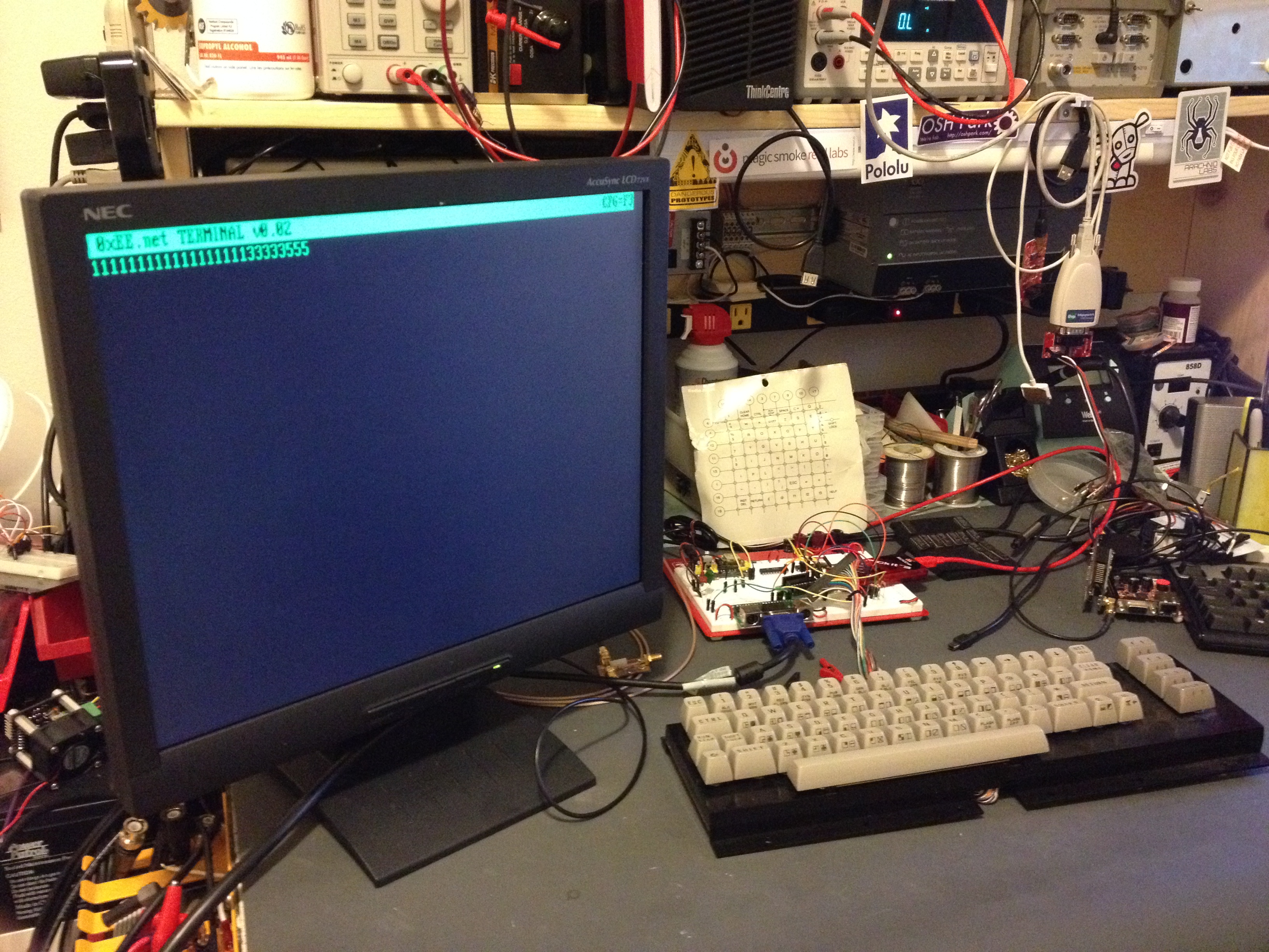
Okay before you start; I know.. I know.. Because I’m shooting for a VT-100-ish emulation my project is technically an “intelligent” terminal but not in a sense that it runs an embedded OS/IP-based, but in the sense that it decodes ANSI ESC codes.. it’s still a freakn’ dumb terminal in my book.
I’m just about finished with the PC board for this and in the photo below is my proof of concept. All the key’s don’t work yet as I don’t have enough IO without some encoding; the keyboard is an old row/column keyboard I scored off eBay. Because I want to stick with a smaller PIC I’m going to use 74HC series logic to accomplish this, but I was considering switching to CPLD in a version 2.
My PIC 18F14K22 Dumb Terminal
Target Features: Baud change (to terminal) via a config screen on the fly (likely limited it to 1200, 2400, 4800, 9600, 115k). Switching the “retro” color from green, amber, or if you’re boring/have been playing too much telehack, white. Half/Full duplex… no color decoding (or VT220 emulation) but perhaps in the future.
Once my PC board is finished and back from the fab I’ll finish the code and make a proper post… the code isn’t presentable besides at least being decently commented. When will you see my next post on this?….. read on.
I have collaborated with Francesco of GarageTech to create a new site. Francesco had some really good ideas, so I pushed 0xEE.net off to its own site. We’re just ironing out a few details and starting our first articles… look for some good stuff soon! 0xEE.net will be ALL PIC-based… I’m pushing all my PIC based projects over there. I’ll co-post and maintain my blog for all non-PIC based stuff .. but if I’m dropping code and it’s not snippets, I’ll post a generic tidbit and a description here and link in over to 0xEE.
If you’re curious: it’s also not lost on me that you could use RealTerm or PuTTY on your PC… I just think this is nifty if you have the bench space.
Who needs more kids when there’s spectrum analyzers to be had!
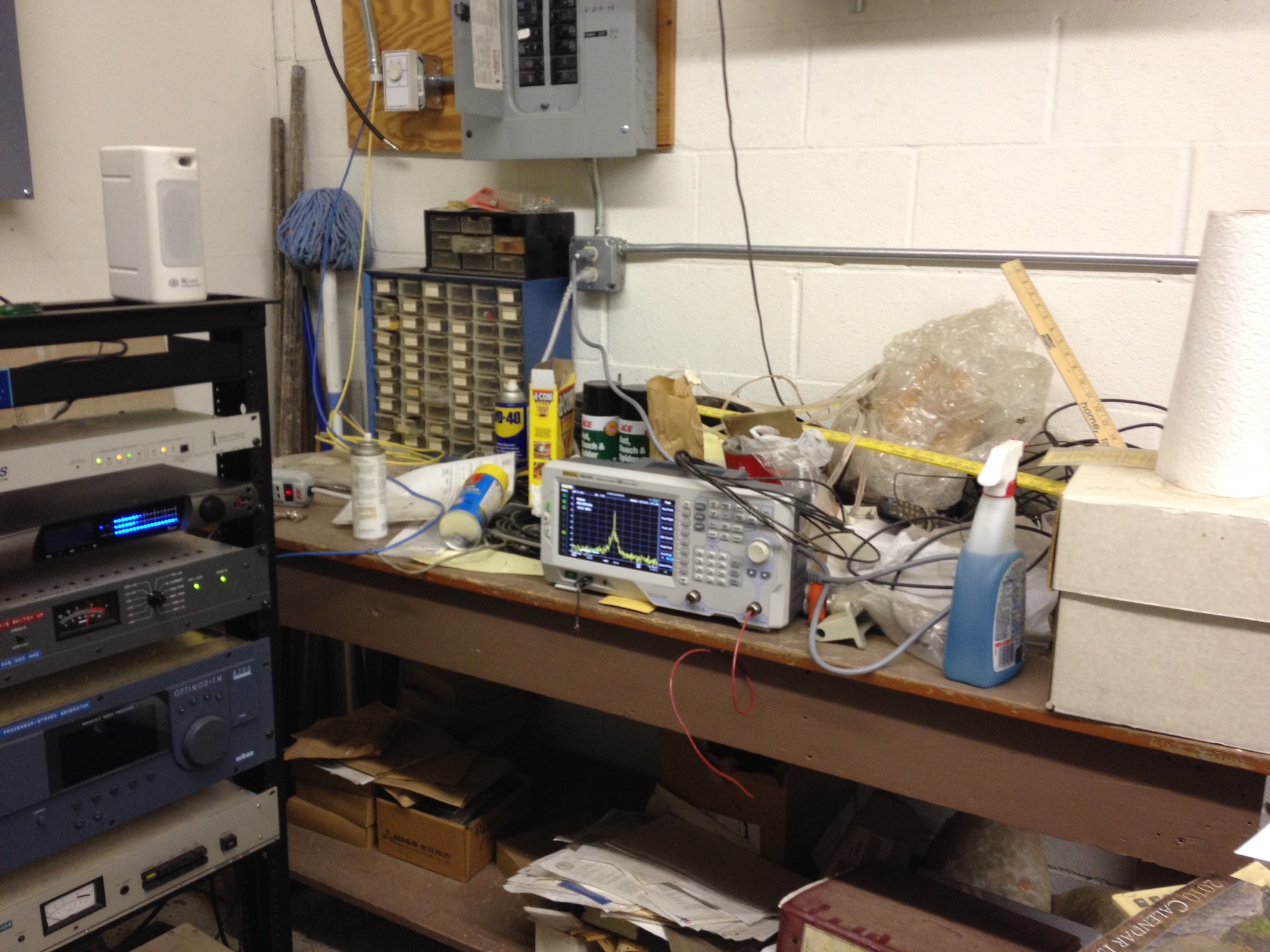
My new Toy! The Rigol DSA 815 Spectrum Analyzer
I haven’t had a lot of time to play with this because well, I just got it. I will sit down and really tear it up … I have filters-galore to design and tune now!
Someone said they needed to take photos of the screen but there is a USB port and it does a find job of taking a snap shot to a drive.. maybe I have a new revision?
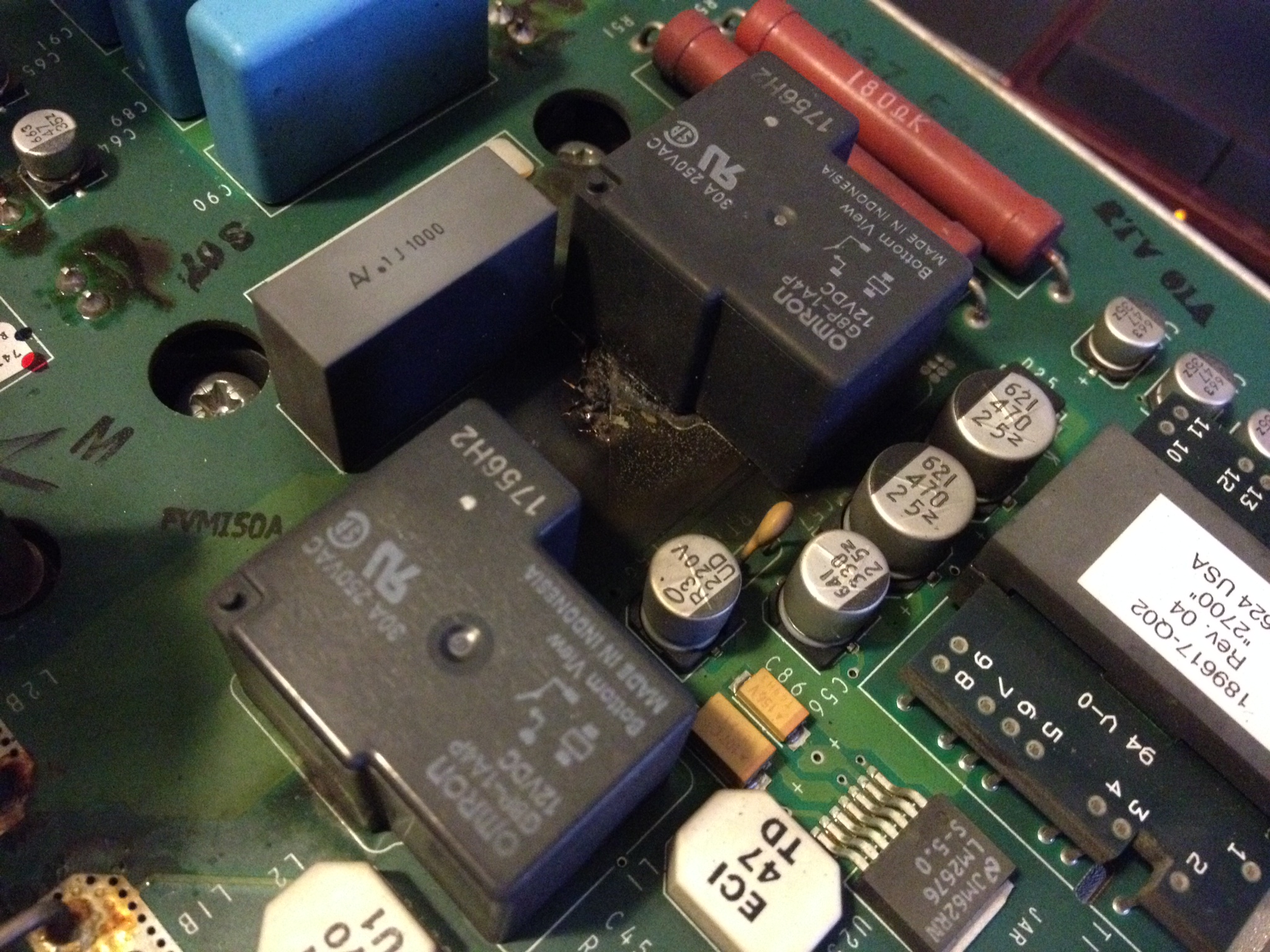
.. Next up.. Thursday night I picked up another VFD.. I have been looking for a smaller drive.. well unfortunately this one was really dead. After I pulled this board I looks like there was massive arcing to the ground plane. I also noticed the main inductor was cooked and the IGBT pack looked toasted.. this must have made a little noise went it went! At least I got a nice heat sink with fans out of the deal.
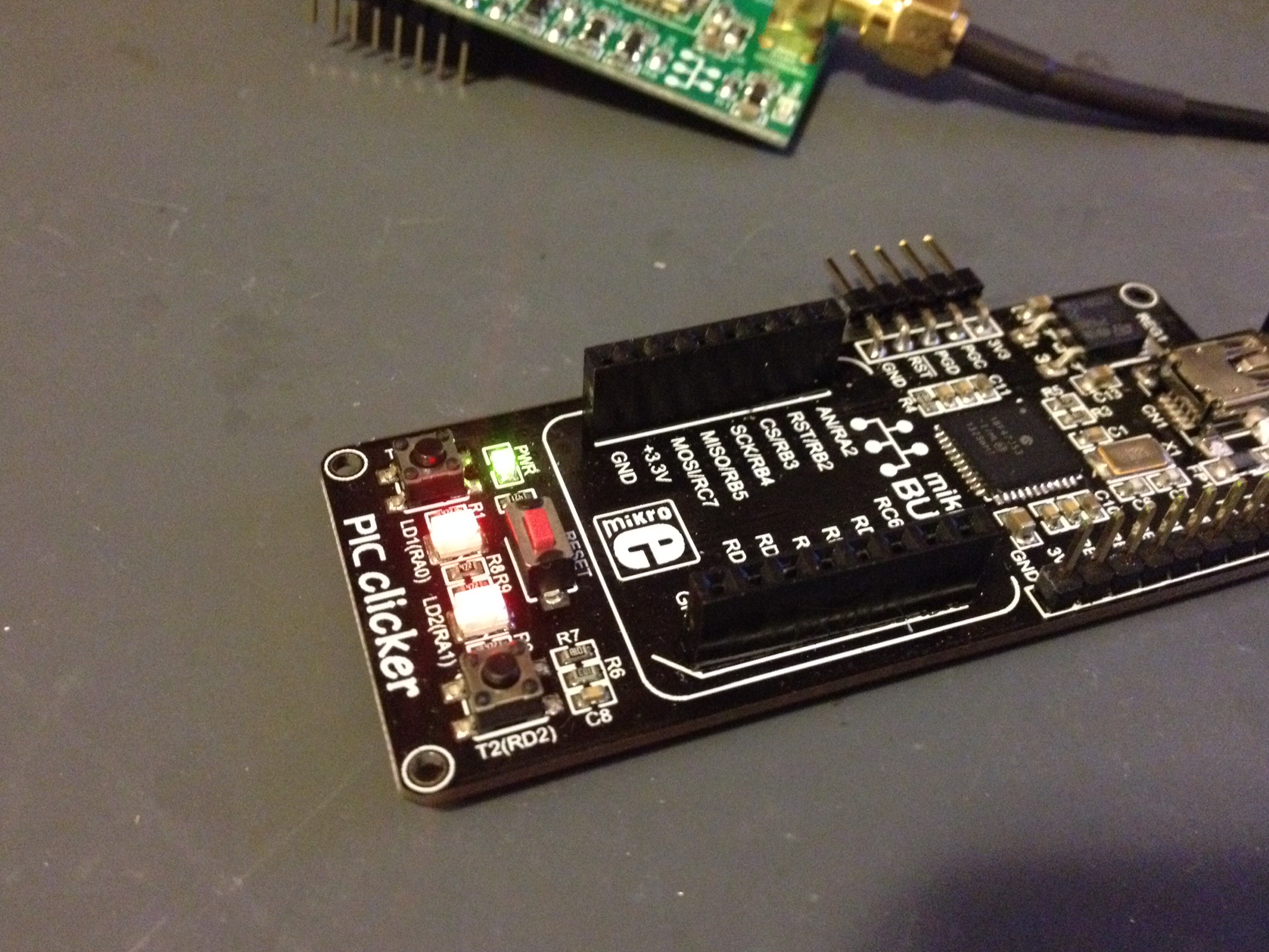
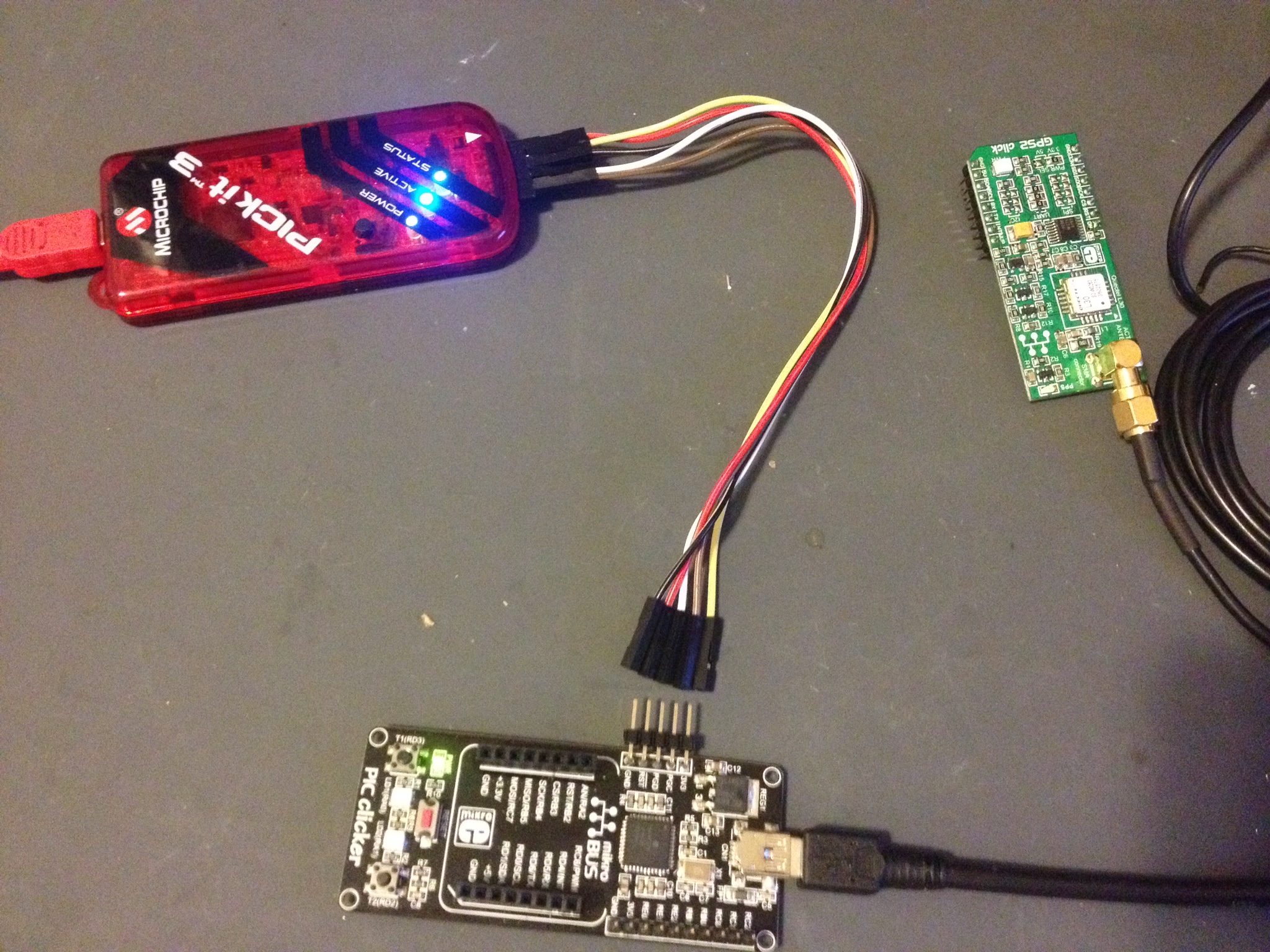
Back to this last weekend: I am not going into what I’m working on because that’s a post for another day. I am working on something with my PIC Clicker… I accidentally toasted the boot loader because I was throwing caution into the wind and felt like using my PICKit3 to program it… no need for any Mikroe C stuff… but in good faith of trying this out I reloaded the boot-loader from the hex file they provide online (thanks guys), downloaded Mikroe C, and have been writing code with it. I don’t like the change, meh. I can say if I was starting all over it would have been easier starting with one of the EasyPics or PIC Clicker and MikroeC. Lets see how it goes. Below is my first “hellow world” program blinking the LEDs..
.. so if you feel like hooking your Clicker up to the PIC kit.. here is how I did it. The colors are in order there.. just pulled off the clicker.
I have hope of finishing up one project “mostly-enough” to post it mid week..
I took an old milli-volt meter which is long dead and gutted the case. It was a lucky day when I could just flip the face plate over and I had a ready-made front plate for my frequency standard. I got my power supply in yesterday from Digi-Key. It was $19 1470-2284-ND … 15V 50W. I will down convert what little 5V power I need off that. AC is wired in, tested, power supply is good to go. I have only thought of one addition to just the basic standard. A phase detector. I’ve selected a desired circuit and I would love feedback from others. I think I will have an input signal drive a high speed comparator which will feed one side of an XOR gate, and then another comparator driven with the 10MHZ signal from the FS. I’ll then throw that up on the analog meter.. the idea is if there is any frequency drift you’ll see the signal increase of decrease with the XOR (phase detector) on the analog meter. Any neat ideas for additional features?
Newly mounted Rubidium Frequency Standard and switching power supply
WWVB transmitter:
I have a solid transmitter now.. I need to finish the circuit (within Eagle CAD) and send it to the fab. Picking a microcontroller would help too. I like the 18F26K22 but they have a lead time of June @ Digikey. I’m thinking the 18F14K22 will probably work. I don’t need the IO.
IBM POS 40 character display:
Well I received this 40 character LCD display (for $9 off eBay) yesterday… Adam Fabio conned me into making the purchase 😉 Yesterday I spent six solid hours of reading and watching my logic analyzer. This display driver has me baffled at what the protocol it wants. I’m sure it’s RS-485, most likely 9600 baud.. and the 87C52 processor has a t2 (timer 2?) output XORing the RS-232 signal after driver/receiver with a 2Hz square wave. That’s odd.. I hung up that project for now.. maybe I’ll get lucky and stumble into a signal protocol description.
PIC Clicker/GPS2 click:
Zero progress from Saturday. I think this will be my next week entertainment while I’m out-of-town. I’ve packed a little electronics-go bag 🙂
Color Synth and Sequencer:
I ordered my spectrum analyzer for filter building. It should be here just into the new week next week which kind of sucks because I’m out-of-town for training. I’m very excited to have a spectrum analyzer. I purchased a bunch of SMA cabling, adapters, made an sample attenuator for it. I almost bought a used one but in the end I just bought new. I’m sure it’ll make it into a few posts.
I’ve been a little busy on the workbench lately. I’ve been working late at the-day-job so I’ve been neglecting my workbench notebook and my blog for most of this week. I’ve got a ton of “fun” stuff planned for this weekend; no way I’ll get it all done.
I won’t make you read through the whole post if I pulled you in with mouse hacking 😉
I am a poor gamer.. give me a cheat code and I’ll use it. I have no shame in gaming. Adam Fabio recently got me slightly addicted to ClickingBad … I refuse to link it, don’t search for it.. it’s a god-awful time suck. I clicked a freakn’ mouse for 90 minutes straight… Well screw that. I pulled out one of those el-cheapo USB mice you get with a refurb computer… the $5 throw-away kind. I popped it open and as luck would have it little microswitchs on a single sided PCB. Well 2-1/2 minutes later I had soldered wires to the switch contacts, dumped them on the normal open contacts of a small relay, hooked it up the relay coil to my MOSFET driver (yes, way overkill, it was laying there already), and threw it under a PIC. I used a rate of 70 ms off 40 ms on.. I probably could have sped that up but it was at that warp speed, I was happy. Did it take away from the game? Nah, I had that much more to buy! I was shocked the relay held out for a few days of being hammered (“Batches hand-cooked: 1.01Q” , that’s not a quadrillion clicks, but it was a lot regardless). I pulled my cheat-clicker off after a while because the super-fast click of the relay was getting pretty damn annoying. I had little bug in the system: a little phantom drift issue with the el-cheapo mouse so turned down pointer sensitivity to as slow as possible; That allowed for a couple hour stretch of non-stop cheating.
Continuing on with actual electronics projects: I have five active projects I’m working on, a few I’ve recently benched waiting on a big purchase, trying to get other stuff out of the way or for other reasons.
1. Video Synth … Lawrence has inspired me to help him build a Video Synth. I’ve gotten a fair amount of reading done. Looks like I’m going to need a spectrum analyzer for some filters I want to build (awww darn! heh). I’ve gotten some boards finished which I needed for other projects but just happened to work for this one as well.
Sweep Generator — Opps I forgot something
… version 2.0 of these boards in at the fab. I’ll probably sell some of these for people needed a quick sweep generator for their VCOs, etc.
2. Workshop Time Standard — Just started this because I got most of the parts in. This will be powered by my MikroElectronika PIC clicker and GPS2 click…. Stay Tuned.
3. WWVB for non-US persons… Edward contacted me about using my WWVB project but to actually broadcast the correct time. Well, fair enough. This has gotten me to buy all the stuff I think I need to create a PIC NTP client, GPS NMEA input .. and then the easy part. Broadcast it on 60KHz… I’ll have some kind of notice you should do this in a lead box under the ocean. I certainly wouldn’t sell this to someone within the US. I don’t think the FCC has any rule that allows a person to broadcast any tiny amount of power on 60KHz, certainly not intentionally. I didn’t find anything I thought I’d be safe under Part 15. I’d love to be proven wrong on this.. really.
4. My electric scooter. I just got a welder … now for some more material. Most of the electronics are done-enough until testing.
5. My ESR meter… waiting on parts of course.. come on Customs.. let me have my fun-stuff.
… all this work has left me bench a disaster zone.
Jayson Tautic had mentioned, on IRC the other day, a Fourth system with the ability to run on a PIC… that pretty cool (mad scientist stuff!). It prompted me to consider connectivity; I posted my progress on the recent Digi One SP project that came out of that on my last post.
It’s been noticed that Jayson sleeps far fewer hours than I do, this is further proof! At lightning speeds (maybe that’s why he sells a lightning sensor?) he has his Pi running ser2net which connects the internet to a terminal port and from there to the serial port of his PIC running FlashForth. Jayson has Forth running on an 18F14K22 on his 20pin dev board which can also be found on his tindie store. I have never reviewed/commented on someone else’s project but I thought this was extremely clever and demanded attention. He won’t admit it was much of course, he’s far to modest. What’s next? What does this open up for us 8-bit PIC developers? Well I tell you what.. I have some ideas you’ll see in the near future!
I had a need for this little break-out-board for a bunch of RGB LEDs I had acquired. Have a need?
A special deal to get rid of the boards and LEDs with “unknown” specs. These LEDs look just like the 60mA LEDs from China but I don’t have any specs on these. I based my design on LEDs I have coming in stock.. well unfortunately these LEDs have the blue and green swapped so I took an exacto-knife to pull of the stencil stating which is R, G and B… I want to get rid of these so I’m going to cut you a deal: what do you get? an extra board and an extra LED! A practice board for reflow! These are full functional parts and pieces. I’ve tested every LED on all boards.
Here is what you’ll receive:
In the photo you’ll see the arrows. The black arrow represents the negative side of your supply and the colored arrows correspond to the color of the positive (anode) side of each LED.
In version 1 of this board I’ve added 100 Ohms resistors. These are the values I needed for my project. If you really happen to need other values let me know and I’ll see what I can do. These work fine on 3.3V as well as 5V.


