Today was a FR4-AIL day, again. Still no PCBs in the mail today; I suspect this will be a PITA because they never left the Oregon post office.
With that I wasn’t really in the mood for any “real” electronics today. Jayson Tautic mentioned he put Fourth on a PIC 18F14K22 which is pretty cool. It got me thinking, one thing and then another and on to connectivity which lead me digging into the old project bins.
I’m sure it’s been done over and over but it hasn’t been done by me; I’ll see if I can put a PIC online. Maybe a simple text game?
Out of the projects bin came a Rev A11 XPort… well an hour later it went right back into the box. I think the old versions weren’t really friendly for what I was thinking.. next attempt was a Digi One SP. I bought one off eBay a while back; I’m way more familiar with these as I had installed a couple of them for a radio station for some telemetry.
EdgePort/i (USB to RS232) to Null Modem Adapter to Digi One SP to ethernet..
The whole set up on the Digi One SP is pretty easy; logon by web browser, set up a static IP, etc, etc… the only tricky part was Serial Port set up. It would seem the Serial Port Profile setup should be to the “Modem In” profile but in fact to initiate a connection from ethernet you need to choose “Modem Out”. No problem..
So this is how I tested the setup:
I used RealTerm to connect to the serial port, it’s ANSI emulation but I used ASCII so I could the control characters. I connected my EdgePort (USB<–>RS232) through a null modem adapter to the DigiOne SP. On the ethernet side I used Putty; with a little poking I connected to the Digi One with “RAW” TCP to port 2001.
Digi One SP Serial Link Test
The connection tidbits are done, now I have to order a wireless bridge so I can get an ethernet port down in my bench (all wifi)… in the mean-time I also set up dyndns with my router because we don’t have a static IP address… TBC.
To be honest, I have never considered using the PIC 16F1509 digital to analog converter before. I was considering integrating a DAC internally or externally to a microcontroller for my brother’s synth project. I started on the microchip site and found a number of smaller PICs, 12F1501.. 16F1503, that had a 5bit DAC. The 16F753 has a 9bit and the 16F17* series has a 8bit DAC. I stuck with the old standby 16F1509 as I needed a serial port for MIDI and I had it sitting on an easy-to-use dev board. I ordered a 16F17* series PIC a while back because they have some interesting peripherals and I will probably build a board around it for the resolution.
Turns out the DAC is probably the easiest peripheral I’ve used on the PIC. It took me longer to wait for the PICKit to update from 18F configuration to 16F. BUT.. if you’re having issues.. here you go:
A simple voltage follower (or however you want to buffer the output) is needed on the DAC output. It’s not designed to drive anything.
Don’t expect screaming speeds out of this thing…it’s just not going to happen. I ran mine up to 1.3KHz, which is more than enough for what I’m trying to accomplish. If you put an A/D converter in you could use that to control your ramp speed and you’d have yourself a nice driver for your VCO input on test equipment with properly conditioned output.
Digital to Analog converter on the PIC 16F1509; The 5bit DAC gives you 32 voltage levels.
The code:
/*
* File: main.c
* Author: Charles M Douvier
* Contact at: http://iradan.com
*
* Created on April 13, 2014, 1:14 PM
*
* Target Device:
* 16F1509 on Tautic 20 pin dev board
*
* Project: DAC ramp test
*
* Version:
* 1.0
*
*/
#ifndef _XTAL_FREQ
#define _XTAL_FREQ 4000000 //4Mhz FRC internal osc
#define __delay_us(x) _delay((unsigned long)((x)*(_XTAL_FREQ/4000000.0)))
#define __delay_ms(x) _delay((unsigned long)((x)*(_XTAL_FREQ/4000.0)))
#endif

#include
#include
#include
#include

//config bits
#pragma config FOSC=INTOSC, WDTE=OFF, PWRTE=OFF, MCLRE=ON, CP=OFF, BOREN=ON, CLKOUTEN=OFF, IESO=OFF, FCMEN=OFF
#pragma config WRT=OFF, STVREN=OFF, LVP=OFF

#define _XTAL_FREQ 4000000 //defined for delay

int x; //DAC counter

/*
*
*/
void init_io(void) {
TRISAbits.TRISA0 = 0; // output
TRISAbits.TRISA1 = 0; // output
TRISAbits.TRISA2 = 0; // DAC2
TRISAbits.TRISA3 = 0; // output
TRISAbits.TRISA4 = 0; // output
TRISAbits.TRISA5 = 0; // output
// TRISAbits.TRISA6 = 0; // output
// TRISAbits.TRISA7 = 0; // output

ANSELA = 0x00; // all port A pins are digital I/O

TRISBbits.TRISB4 = 0; // RB4 = nc
TRISBbits.TRISB5 = 1; // RB5 = nc
TRISBbits.TRISB6 = 0; // RB6 = nc
TRISBbits.TRISB7 = 0; // RB7 = nc

ANSELB = 0x00; // all port B pins are digital I/O
TRISCbits.TRISC0 = 0; // output
TRISCbits.TRISC1 = 0; // output
TRISCbits.TRISC2 = 0; // output
TRISCbits.TRISC3 = 0; // output
TRISCbits.TRISC4 = 0; // output
TRISCbits.TRISC5 = 0; // output
TRISCbits.TRISC6 = 1; // input
TRISCbits.TRISC7 = 1; // input
ANSELC = 0x00; // all port B pins are digital I/O
}

void init_dac(void)
{
DACCON0bits.DACPSS = 0; //VDD ref
DACCON0bits.DACOE2 = 1; //output 2 enable (RA2)
DACCON0bits.DACEN = 1; //enable DAC
}

int main(void) {

// set up oscillator control register, using internal OSC at 4MHz.
OSCCONbits.IRCF = 0x0d; //set OSCCON IRCF bits to select OSC frequency 4MHz
OSCCONbits.SCS = 0x02; //set the SCS bits to select internal oscillator block
OPTION_REGbits.nWPUEN = 0; // enable weak pullups (each pin must be enabled individually)

init_io();
init_dac();

x = 0;

while (1) {

for (x = 0; x < 31; ++x)
{ //DAC is 5 bit
DACCON1bits.DACR = x; //dump count into DAC value
__delay_us(25);
}

}
return (EXIT_SUCCESS);
}
Today I received the first of a couple batches of PCBs from OSH Park. This set is a simple MOSFET w/ driver. The MOSFET can be logic level driven and all my testing was done at 5VDC however the driver had a wide voltage range so running this at 9V or 12V should present no issues (16V max! VGS). I do have a few minor adjustments I want to add (silk screen additions and adjustments). I built this board as an electric scooter motor drive and I tested it with the motor I was interested in using and thankfully all testing worked out well including loading my power supply at max load for over an hour straight 🙂 This board can be used for an assortment of load control applications.
The build was easy enough, next board I think I’ll just skip the chipquik and stick to straight soldering iron… and I think I also “figured out” the trick to solder the heat sink without making too much of a mess.
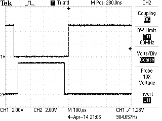
I tested the load for 60 minutes at 66% duty cycle and 1.5KHz PWM with total load at 140watts (45Volts 3.1 Amps).. the heat sink temperature on the MOSFET raised from ambient (78 deg F) to 90.7 deg F (32.3 deg C) steady for an hour. The MOSFET is rated for 55V (max) at 30 amps but the board isn’t designed to handle that load. I used 50mil power traces which is roughly 3 amp handling according to the google machine; 5A if you don’t mind a 40 deg C rise (though there is a fan) so I’ll call this a 140W MOSFET board (47×3). I personally feel I could squeeze more current out of this in short bursts but I would need to do more testing.. and I can’t promise anything along those lines. The PWM signal was generated and directly fed from a PIC 18F16K22 microcontroller running @ 5V. You’re NOT going to be able to drive this at 3.3V.
Fresh off the soldering iron!Driving an electric scooter motor. Note the diode for flyback near the bottom of the photo just hanging out. The flyback diode is a must in this application.MOSFET PWM signal vs VDSS
I will likely stick a 75VDSS MOSFET in the next revision…
.. I’m considering selling these on Tindie. If you’re interested in getting on of these “BETA” boards at cost let me know before they’re gone.
Took a while to clear off the bench tonight. I got a little happy with the ORDER button last week through weekend. I’ve filled two more parts storage containers and luckily one of my new packages with another parts storage container from Amazon; I couldn’t find any locally, I hope they’re still making them.
The last thing I got to was this “Gauge Stepper Breakout” I got off The Rengineer (The Renaissance Engineer)’s Tindie store. Adam took this very nice stepper motor, put a gauge needle on it (which I believe he 3D printed, or at least it looks like it) and some nice diodes for voltage protection. What’s great about this board is you can drive it right from your microcontroller. I’m sure I don’t need to tell you how weird that is.. I worry about big LEDs.. but here this stepper was happy as a clam being powered by my PIC. I still might consider at least buffering this if I was to place it in a permanent circuit.
Adam’s provides links to some Arduino libraries but he was saved me a ton of time and just happened to have some PIC sample code! Not before I had about 75% of a ECCP program completed. (I’ll link some of that code if you’re looking for an example of Enhanced PWM output). Once I had Adam’s code I ported it to the TAUTIC 18F26K22 dev board because I already had one on the breadboard. That was mostly changes in the TMR0 (timer 0) code. The only thing of note is check out my IO comments for wiring. You have to cook up 5V/GND to this board then I drove RC3 –> A1 RC2 — A2, RC1 –> B1 and RC0 –> B2. When I had it flipped around the stepper moved in the opposite direction of how I wanted.
A little video of the code in action:
This code is a little sloppy but I just testing this out and it did the trick:
/*
 * File:   main.c
 * Author: Charles M Douvier  Contact at: http://iradan.com
 * Core Driver Code by Adam F. of http://www.therengineer.com/
 *
 * Created on April 4th, 2014
 *
 * Target Device:
 * TAUTIC PIC 18F26K22 Dev Board
 *
 * Project:
 *
 *
 * Version:
 * 1.0
 *
 */

#ifndef _XTAL_FREQ
#define _XTAL_FREQ 4000000 //4Mhz FRC internal osc
#define __delay_us(x) _delay((unsigned long)((x)*(_XTAL_FREQ/4000000.0)))
#define __delay_ms(x) _delay((unsigned long)((x)*(_XTAL_FREQ/4000.0)))
#endif

#include
#include
#include
#include

//config bits
#pragma config FOSC=INTIO67, WDTEN=OFF, PWRTEN=OFF, CP0=OFF, CP1=OFF, BOREN=ON
#pragma config STVREN=ON, LVP=OFF, HFOFST=OFF, IESO=OFF, FCMEN=OFF

//WRT=OFF, FOSC=INTOSC, MCLRE=ON

#define _XTAL_FREQ 4000000 //defined for delay
#define MIN_STEPS_LEFT 23
#define MAX_ACCEL_INDEX 6
#define MAX_STEP 945 /* motor can move 945 steps from stop to stop*/

    int     an8_value, an9_value;          //value for a/d
    char    buf[10];            //buff for iota
    long int    fvar;           //long for format math
    long int    tens;           //left of decm
    long int    decm;           //decimal places
    int     tempi;              //to add leadign zeros..
    int     vtxdata;             //volts int for TX
    int     itxdata;

    unsigned short defaultAccelTable[][2] =
{
  {   1750, 3},
  {   1149, 3},
  {  926,   3},
  {  794,   3},
  {  709,   3},
  {  666,   4},
  {  /*629*/450,   4},
};
unsigned int currentStep;
unsigned char currentState;
unsigned char stateMap[] = {0x09, 0x01, 0x07, 0x06, 0x0E, 0x08};
unsigned char serialBuffer[10];
unsigned char serialByteCount;
 static const unsigned char stateCount = 6;

    volatile unsigned int uart_data;    // use 'volatile' qualifer as this is changed in ISR
/*
 *
 */
void interrupt ISR() {

    if (PIR1bits.RCIF)          // see if interrupt caused by incoming data
    {
        uart_data = RCREG;     // read the incoming data
        PIR1bits.RCIF = 0;      // clear interrupt flag
    }

}

void init_io(void) {
    TRISAbits.TRISA0 = 0; // output
    TRISAbits.TRISA1 = 0; // output
    TRISAbits.TRISA2 = 0; // output
    TRISAbits.TRISA3 = 0; // output
    TRISAbits.TRISA4 = 0; // output
    TRISAbits.TRISA5 = 0; // output
    TRISAbits.TRISA6 = 0; // output
    TRISAbits.TRISA7 = 0; // output

    ANSELA = 0x00; // all port A pins are digital I/O

    LATAbits.LATA0 = 0;
    PORTAbits.RA0 = 0;

    TRISBbits.TRISB1 = 0;   //P1C output
    TRISBbits.TRISB2 = 0;  // P1B output
    TRISBbits.TRISB3 = 1;  // AN9    speed control 0-5V
    TRISBbits.TRISB4 = 0;  // P1D output
    TRISBbits.TRISB5 = 1; // RB5 = nc
    TRISBbits.TRISB6 = 0; // RB6 = nc
    TRISBbits.TRISB7 = 0; // RB7 = nc

    ANSELB = 0b00001000;     //RB3, AN9

    TRISCbits.TRISC0 = 0; // output to B2 .. reversed to stoke the right direction
    TRISCbits.TRISC1 = 0; // output to B1
    TRISCbits.TRISC2 = 0; // output to A2
    TRISCbits.TRISC3 = 0; // output to A1
    TRISCbits.TRISC4 = 0; // output
    TRISCbits.TRISC5 = 0; // output
    TRISCbits.TRISC6 = 0; // output
    TRISCbits.TRISC7 = 0; // output
    ANSELC = 0x00; // all port B pins are digital I/O
}

void uart_xmit(unsigned int mydata_byte) {

    while(!TXSTA1bits.TRMT);    // make sure buffer full bit is high before transmitting
    TXREG = mydata_byte;       // transmit data
}

void serial_init(void)
{
    //9600 8N1
    // calculate values of SPBRGL and SPBRGH based on the desired baud rate
    //
    // For 8 bit Async mode with BRGH=0: Desired Baud rate = Fosc/64([SPBRGH:SPBRGL]+1)
    // For 8 bit Async mode with BRGH=1: Desired Baud rate = Fosc/16([SPBRGH:SPBRGL]+1)

    TXSTA1bits.BRGH=1;       // select low speed Baud Rate (see baud rate calcs below)
    TXSTA1bits.TX9=0;        // select 8 data bits
    TXSTA1bits.TXEN = 1;     // enable transmit

    RCSTA1bits.SPEN=1;       // serial port is enabled
    RCSTA1bits.RX9=0;        // select 8 data bits
    RCSTA1bits.CREN=1;       // receive enabled

    SPBRG1=25;  // here is calculated value of SPBRGH and SPBRGL
    SPBRGH1=0;

    PIR1bits.RCIF=0;        // make sure receive interrupt flag is clear
    PIE1bits.RCIE=1;        // enable UART Receive interrupt
    INTCONbits.PEIE = 1;    // Enable peripheral interrupt
    INTCONbits.GIE = 1;     // enable global interrupt

         __delay_ms(50);        // give time for voltage levels on board to settle

    uart_xmit('R');         // transmit some data
}

// All this motor and timer code is from Adam with very minor changes to fit the processor

void t0Delay(unsigned int usec)
{
    unsigned int t0ticks; //16 microsecond timer0 ticks
    unsigned char t0Preload;
    if(usec<16)
    {
        t0ticks=1;
    }
    else
    {
        t0ticks = usec/16;
    }
    t0Preload = 0xFF - t0ticks;
    INTCONbits.TMR0IF=0; //clear the flag
    TMR0 = t0Preload;
    while(INTCONbits.TMR0IF==0)
    {
        ;
    }
}

void zeroMotor()
{
    unsigned int i;
    for (i=0; i < MAX_STEP; i++)
    {
        LATC=stateMap[currentState];
        currentState = (currentState + 5) % stateCount;
        t0Delay(1900);  //2200 in datasheet
    }
    //now the motor is zeroed, reset our state variables.
    currentStep = 0;
    currentState = 0;
    LATC=0; //turn off coils
}

void moveMotor(unsigned int targetStep)
{
    unsigned int dir;
    unsigned int curDelay;
    unsigned char speedIndex=0;
    unsigned char stepsAtThisSpeed=0;
    unsigned int stepsLeft;
    if(currentStep<targetStep)     {         dir = 1;         stepsLeft = targetStep-currentStep;     }     else     {         dir = -1;         stepsLeft = currentStep - targetStep;     }     while(stepsLeft>0)
    {
        if(stepsLeft<=MIN_STEPS_LEFT)         {             //decellerating             if(stepsAtThisSpeed==0)             {                 if(speedIndex>0)
                    speedIndex--;
                curDelay=defaultAccelTable[speedIndex][0];
                stepsAtThisSpeed=defaultAccelTable[speedIndex][1];
            }
        }
        else
        {

            //accellerating or steady state
            if(stepsAtThisSpeed==0)
            {
                if(speedIndex<MAX_ACCEL_INDEX)                 {                     speedIndex++;                     curDelay=defaultAccelTable[speedIndex][0];                     stepsAtThisSpeed=defaultAccelTable[speedIndex][1];                 }                 //else we're at steady state - do nothing.             }         }         //write step         LATC=stateMap[currentState];         if(dir==1)         {             currentState = (currentState + 1) % stateCount;         }         else         {             currentState = (currentState + 5) % stateCount;         }         t0Delay(curDelay);         if(stepsAtThisSpeed>0)
        {
            stepsAtThisSpeed--;
        }
        stepsLeft--;
        currentStep+=dir;
    }
}

int main(void) {

    init_io();
    serial_init();

    // set up oscillator control register, using internal OSC at 4MHz.
    OSCCONbits.IRCF = 0x05; //set OSCCON IRCF bits to select OSC frequency 4MHz
    OSCCONbits.SCS = 0x02; //set the SCS bits to select internal oscillator block

    ADCON0 = 0b00100101;                            //select AN9 and enable
    ADCON1 = 0b00000000;                  //speed Vref=AVdd, VssRef=AVss
    ADCON2 = 0b00111011;                //ledft justified, 20RAD, FRC

    INTCONbits.TMR0IE = 0;

    TMR0=0;

    T0CONbits.T08BIT = 1;
    T0CONbits.T0CS = 0;
    T0CONbits.PSA = 0;
    T0CONbits.T0PS = 0x04;
    INTCONbits.TMR0IF = 0;

        T0CONbits.TMR0ON = 1;

    __delay_us(5);

    currentStep = 0;
    currentState = 0;

    zeroMotor();
    __delay_ms(149);        //this could be less messy
    __delay_ms(149);
    __delay_ms(149);
    __delay_ms(149);
    __delay_ms(149);
    __delay_ms(149);
    moveMotor(20);
    __delay_ms(149);
    __delay_ms(149);
    __delay_ms(149);
    __delay_ms(149);
    __delay_ms(149);
    __delay_ms(149);

    moveMotor(940);
    moveMotor(5);

    while (1) {

        //PORTAbits.RA0 = 1;      //heart beat
        //__delay_ms(50);
        //PORTAbits.RA0 = 0;
        //__delay_ms(50);

        ADCON0 = 0b00100101;    //select AN9 and enable
        __delay_us(5);
        GO = 1;
        while (GO) continue;    //wait for conversion
        an9_value = ADRESH;     //AN9 value

        fvar = an9_value;
        fvar = fvar * 10749;    //calibration.. change to meet your needs
        fvar = fvar / 256;
        tens = fvar / 100;
        //tens = tens % 10;
        decm = fvar % 100;
        vtxdata = fvar / 20;
        uart_xmit(vtxdata);    // -->RS232

        moveMotor(vtxdata);
        //moveMotor(5); //from sample code
    }
    return (EXIT_SUCCESS);
}
Some ECCP ( Enchanced PWM ) code written for the PIC 18F26K22 code I wrote following the screen shot of the output:
My wife is kicking all non-food items out of the Frig… time to find a new place for the Chip Quik!
Chip Quik is a brand of solder paste used often in hobbyist reflow; this is the product I used to solder SMD parts to printed circuit boards. The product can work six months (or longer in reality) if you keep it cooled.
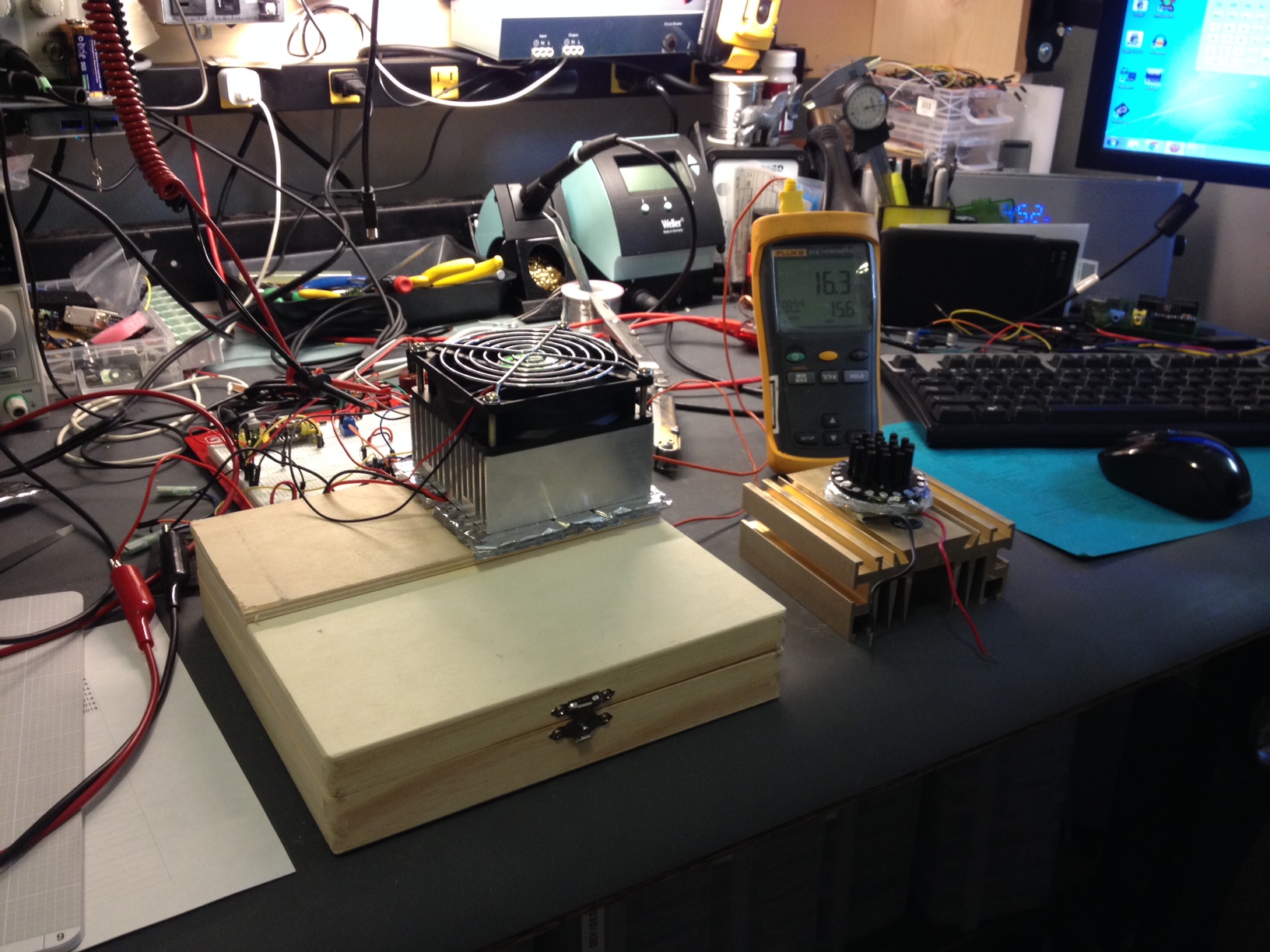
What to do? Well I started by looking into small frigs.. too much power and they cost too much. Next was the obvious choice: A peltier cooling device and a box. It took me a while to find *anything* that was small and seemed like it would work on my bench as well as be able to be insulated. I went to Lowes and picked up a roll of foil bubble-wrap looking insulation, a trip to a hobby store scored me this wooden box. A little hot glue and a start with two surplus heat sinks (seen rejected and removed to the right in the photo)
A simple chip quick cooler and his failed cousin.
The inner heat sink had a fan, exterior heat sink didn’t but didn’t get uncomfortably warm. It didn’t work as I had hoped though; I couldn’t pull off more than about 10 deg F delta T from the ambient temp in the room…. not going to be good enough. My workshop hovers around 78-85 deg F due to heat load of the items… Chip Quik isn’t going to last more than the six months rating in those temps.
The search for a solution continued, I picked up a little peltier kit off eBay to see if I could do better; easy enough I guess. Put it all together and now I’m getting about 25-30 deg F delta T from ambient. My little box settles out fairly quickly at about 58 deg F (15 deg C) which is good enough. Next I’ll do some clean up and power this with a PC power supply. I’ll use a spare PC power supply because I don’t want to use up a bench supply and like it or not these devices to draw some current. It’ll take about 25%-50% of the power of the smallest frig I could find to keep this thing cooling .. though the frig would be great for some beer pop, unfortunately I don’t have the room.
Alternative ideas to this problem are welcome.
I have a ton of projects right now and zero parts… wait wait wait.. I hate waiting for parts 🙂 … come on slow boat from China! I also have a board in OSHPARK I’m super excited about, but no sneak peaks…. it’ll be here soon enough. Wait wait wait wait…
I’m considering building an electric scooter; considering it probably putting it lightly.. I have almost everything I need for it. Interested? Why type so much when you can just watch my proof of concept!
If you’re following along and want to use the same hardware (warning totally untested… ):
Controller found on the TAUTC Tindie Store
Search on eBay for “24VDC scooter motor” ..
..and pick up a MOSFET that’ll pull off a couple 20 amps and saturates at or below 5VDC.
…what am I talking about? Try google or read this.
To the important stuff, the code:
/*
 * File:   main.c
 * Author: Charles M Douvier
 * Contact at: http://iradan.com
 *
 * Created on March 27, 2014, 4:12 PM
 *
 * Target Device:
 * 18F26K22 on TAUTIC Dev Board
 *
 * Project:
 * Electric Scooter
 *.. a real hack job, comment, delete garbage, etc.
 *
 * Version:
 * 0.1
 *
 */
#ifndef _XTAL_FREQ
#define _XTAL_FREQ 4000000 //4Mhz FRC internal osc
#define __delay_us(x) _delay((unsigned long)((x)*(_XTAL_FREQ/4000000.0)))
#define __delay_ms(x) _delay((unsigned long)((x)*(_XTAL_FREQ/4000.0)))
#endif

#include
#include
#include
#include

//config bits
#pragma config FOSC=INTIO67, WDTEN=OFF, PWRTEN=OFF, CP0=OFF, CP1=OFF, BOREN=ON
#pragma config STVREN=ON, LVP=OFF, HFOFST=OFF, IESO=OFF, FCMEN=OFF

//WRT=OFF, FOSC=INTOSC, MCLRE=ON

#define _XTAL_FREQ 4000000 //defined for delay

//clean up on isle 2..

    int     an9_value;          //value for a/d
    char    buf[10];            //buff for iota
    long int    fvar;           //long for format math
    long int    tens;           //left of decm
    long int    decm;           //decimal places
    int     tempi;              //to add leadign zeros..
    int     vtxdata;             //volts int for TX
    int     itxdata;

    volatile unsigned int uart_data;    // use 'volatile' qualifer as this is changed in ISR
/*
 *
 */
void interrupt ISR() {

    if (PIR1bits.RCIF)          // see if interrupt caused by incoming data
    {
        uart_data = RCREG;     // read the incoming data
        PIR1bits.RCIF = 0;      // clear interrupt flag
    }

}

void init_io(void) {
    TRISAbits.TRISA0 = 0; // output
    TRISAbits.TRISA1 = 0; // output
    TRISAbits.TRISA2 = 0; // output
    TRISAbits.TRISA3 = 0; // output
    TRISAbits.TRISA4 = 0; // output
    TRISAbits.TRISA5 = 0; // output
    TRISAbits.TRISA6 = 0; // output
    TRISAbits.TRISA7 = 0; // output

    ANSELA = 0x00; // all port A pins are digital I/O

    TRISBbits.TRISB3 = 1; // AN9
    TRISBbits.TRISB4 = 0; // RB4 = nc
    TRISBbits.TRISB5 = 1; // RB5 = nc
    TRISBbits.TRISB6 = 0; // RB6 = nc
    TRISBbits.TRISB7 = 0; // RB7 = nc

    ANSELB = 0b00001000;     //RB3, AN9

    TRISCbits.TRISC0 = 0; // output
    TRISCbits.TRISC1 = 0; // output
    TRISCbits.TRISC2 = 0; // output
    TRISCbits.TRISC3 = 0; // output
    TRISCbits.TRISC4 = 0; // output
    TRISCbits.TRISC5 = 0; // output
    TRISCbits.TRISC6 = 1; // input
    TRISCbits.TRISC7 = 1; // input
    ANSELC = 0x00; // all port C pins are digital I/O
}

void pwm_init(){

//         PSTR1CONbits.STR1A
//hackhackhackhack... TODO

//    CCPR1L = 0x120;
    CCPR1Lbits.CCPR1L = 0xFE;
    PR2 = 0xFE;
    CCPTMRS0bits.C1TSEL = 0;     //CCP TMR2 Selection
    CCP1CONbits.P1M = 0x00;
    CCP1CONbits.DC1B = 0x00;
    PWM1CONbits.P1RSEN = 0;
    T2CONbits.T2CKPS = 1;  //1:2 Prescale
    T2CONbits.TMR2ON = 1;  //timer 2 go

    CCP1CON = 0x0C;       //PWM (CCP)1 ON

}

void uart_xmit(unsigned int mydata_byte) {

    while(!TXSTA1bits.TRMT);    // make sure buffer full bit is high before transmitting
    TXREG = mydata_byte;       // transmit data
}

void serial_init(void)
{
    //9600 8N1
    // calculate values of SPBRGL and SPBRGH based on the desired baud rate
    //
    // For 8 bit Async mode with BRGH=0: Desired Baud rate = Fosc/64([SPBRGH:SPBRGL]+1)
    // For 8 bit Async mode with BRGH=1: Desired Baud rate = Fosc/16([SPBRGH:SPBRGL]+1)

    TXSTA1bits.BRGH=1;       // select low speed Baud Rate (see baud rate calcs below)
    TXSTA1bits.TX9=0;        // select 8 data bits
    TXSTA1bits.TXEN = 1;     // enable transmit

    RCSTA1bits.SPEN=1;       // serial port is enabled
    RCSTA1bits.RX9=0;        // select 8 data bits
    RCSTA1bits.CREN=1;       // receive enabled

    SPBRG1=25;  // here is calculated value of SPBRGH and SPBRGL
    SPBRGH1=0;

    PIR1bits.RCIF=0;        // make sure receive interrupt flag is clear
    PIE1bits.RCIE=1;        // enable UART Receive interrupt
    INTCONbits.PEIE = 1;    // Enable peripheral interrupt
    INTCONbits.GIE = 1;     // enable global interrupt

         __delay_ms(50);        // give time for voltage levels on board to settle

    uart_xmit('R');         // transmit some data "restart" notification
}

int main(void) {

    init_io();
    serial_init();
    LATCbits.LATC2 = 0;
    pwm_init();

    // set up oscillator control register, using internal OSC at 4MHz.
    OSCCONbits.IRCF = 0x05; //set OSCCON IRCF bits to select OSC frequency 4MHz
    OSCCONbits.SCS = 0x02; //set the SCS bits to select internal oscillator block

    ADCON0 = 0b00100101;                            //select AN9 and enable
    ADCON1 = 0b00000000;                  //speed Vref=AVdd, VssRef=AVss
    ADCON2 = 0b00111011;                //ledft justified, 20RAD, FRC
    __delay_us(5);

//loop

    while (1) {

        PORTAbits.RA0 = 1; //blinky i'm alive.
        __delay_ms(140);
        PORTAbits.RA0 = 0;
        __delay_ms(140);

            GO = 1;
    while (GO) continue;              //wait for conversion
    an9_value = ADRESH;               //AN9 value

        fvar = an9_value; //this is hacked off another project but works
        fvar = fvar * 10749;        //calibration
        fvar = fvar / 256;
        tens = fvar / 100;
        //tens = tens % 10;
        decm = fvar % 100;
        vtxdata = fvar / 43; //because I'm lazy... I'll change this later.
        uart_xmit(vtxdata);
        CCPR1Lbits.CCPR1L = vtxdata;

    }
    return (EXIT_SUCCESS);
}
Normal if I’m doing a scratch ‘n sniff on a product I bought it myself because it was something I was interested in adding to a project. Truth be told I got this one for free; I won this board off a contest on twitter. So I don’t have any projects this thing is running on or slated for but I can tell if I need something with a bunch of IO, like perhaps a display this will be the board I use. I have a project list and nothing really fits, but that future project list is always growing and shrinking. If you’re curious I have 38 projects on the list in progress or to-be-started 😀 I have a spreadsheet to manage them all on google drive or I’m sure I’d forget half of them. Sorry, I know blah blah… back to what you’re here for…
The MorePi Me
I unpacked the board and soldered it all together. Not a lot to say about it because it’s just a board, four DIP sockets/74HC595’s a couple connectors and 3 resistors. I like that they included sockets; I would have added them myself but sockets is a must on hobbyist boards!
whixr also send me some test code … happy day.
So I hooked this up and dropped code into it last week.. I left it to burn in all week.. and checked it out today; no problems. I put the Pi on bench and hooked up my logic analyzer … works as advertised. Look at the screenshot of the output for how whixr code works. I’ll also include a copy.
I don’t know when they plan on releasing this product but I’m sure it’ll be on their Tindie store page sooner than later. I also know that tymkrs wouldn’t mind donations for their educational work
I could only find one insignificant thing I didn’t like; there is a little ringing on the output of the 74HC595’s.. I did my due-diligence to ensure this wasn’t a false measurement. No biggie, a little load killed the ringing…
I say kudos to the tymkrs for this great product!
The output of whixr’s sample code on the MorePi Me v1
the code!
# MorePi Me v1 Demo by @tymkrs

def update():
for index in range(0, 32):
if state[32 - index]:
GPIO.output(DataPin, GPIO.HIGH)
else:
GPIO.output(DataPin, GPIO.LOW)
GPIO.output(ClockPin, GPIO.HIGH)
GPIO.output(ClockPin, GPIO.LOW)
GPIO.output(LatchPin, GPIO.HIGH)
GPIO.output(LatchPin, GPIO.LOW)

def clear():
for index in range(0, 32):
state[index] = False

state = [False for index in range(33)]

LatchPin = 11
ClockPin = 13
DataPin = 15

import time
import RPi.GPIO as GPIO

GPIO.setwarnings(False)

GPIO.setmode(GPIO.BOARD)

GPIO.setup(LatchPin, GPIO.OUT) #latch
GPIO.setup(ClockPin, GPIO.OUT) #clock
GPIO.setup(DataPin, GPIO.OUT) #data

while True:
for n in range(0, 8):
clear()
state[n + 1] = True
update()
time.sleep(.03)
for n in range(0, 8):
clear()
state[8 - n] = True
update()
time.sleep(.03)
This weekend was a big old waste. I was at the Seattle Mini Maker Faire on Saturday morning.. ran into some of my cousins. It was a fun time.. then Saturday night I had to work from 7:30P to 10A Sunday morning.. that messed up my whole schedule… why? Because I had to change out some old critical controls… this DSC8500 had to be retired… and yes, we are going to Office-Space-it (see note on my demo tape).
So what did I get done? I received my @tymkrs MorePi Me! I don’t think they sell this yet but when they do I’ll drop a link. It’s a Pi expansion board… I set it up and dropped code into the Pi.. it’s been running for a few days burn in time on the Pi.. I’ll check it out later this week and give you the review it deserves. (assuming it doesn’t catch on fire between now and then 😉 thanks whixr & Atidy!
the @tymkrs MorePi Me v1
What else? well amazingly enough I also started working on my Chip Quik bench frig! My wife complains about my Chip Quik in the frig so I want something that can sit in the workshop to keep the Chip Quik in the 40-50 deg F area.. It’s a little box that I insulated with some foil bubble wrap insulation and thin foam. I got the box at a hobby store when my wife was shopping for some yarn. The heatsink is just bench stock and I used a 3A TEC… it doesn’t work well. I get about 15 deg cooler than ambient. It’s not enough so back to the drawing board. I ordered a bigger TEC… bigger heat sinks and well maybe a different box if I have to.
… more coming on this when I get the parts… but here are some photos of my fail.
I don’t know what possessed me to make this video but I decided to go through some of the PIC microcontroller boards I have. I was inspired by my recent purchase of half a dozen of the new TAUTIC 18F26K22 development boards. This was money well spent. I think between this and the 20 pin board I’ll be pretty heartbroken if he stops making the boards.
You can buy many of the boards I reviewed on tindie or microcontrollershop. I didn’t mention that the 20 pin dev board TAUTIC has comes with a 16F1509, I have been dropping 18F14K22 into the board, and I also probably should have mentioned I used to use the ICD2 with the big old dev boards.. I don’t want anyone thinking their PICkit 3 will just plug-in read to go.. you’ll be making or buying a harness of some sort.
I feel like I’ve leaned on video a little too much lately. I’m looking for feedback on this: Love, hate, indifferent?
As a reminder: none of this product came to me for free or even at a reduced price that any one else couldn’t have gotten besides the PIC Clicker which I won randomly online two months ago.
@JohnS_AZ shared his beautiful schematic of a tone sequencer [PDF] he designed with me a few weeks ago. I think he designed it for the @tymkrs ? I watched the video and it looked like a fun project, I wasn’t wrong!
I was shooting for sticking this project into an Altoids tin .. I had low expectations which is good because I’m about 1 cm t0 tall on the trimmers. If I found some lower profile parts and removed my DIP sockets I could pull this off. I’m not that motivated to take care of it but if you want to try you know what to do 😉 I used the Adafruit Altoids tin PCB… I purchased a couple of these a while back; they’re good stuff. The oscillator is up on the top board and then ‘LS90, 4051, VCO and the audio amp are below. I am particularly impressed with John’s use of the Pin 5 input on the LM555 to use it as a VCO; I haven’t seen this done much, usually you’re sticking a cap to ground on this input or letting it float (gasp!). I just have to add some stand-offs and a couple connectors and this project is wrapped up.
My version of his circuit:
Yep, just a little to “thick” to fit in the can… oh well. Stand off’s will work 🙂