..workbench chatter

Melissa and I have been out of town for a little while. I was hoping to blog on the road but it just didn’t happen. That midwest weather is in a nasty way; I don’t miss winter weather at all. So I have a little more work on two posts I’m working on but I wanted to update the blog for if no one else myself. I need a little brain purge… I have a lot of stuff to work on.

When I got home I had a dozen and a half packages or so from China. A ton of fun stuff.. most of it was for the little robot I’m working on. I also brought back a ton of stuff from my house (in a storage room) that I have left behind.

On our travel across county we stopped by our house in South Dakota and picked up a bunch of our items in storage. I brought back a few boxes of miscellaneous electronics including a lot of older projects I built years ago.


Look at that pile of stuff! A part of one box of old projects I built. Only a few more boxes to go! I got excited about a bunch of copper clad board that turned out to be really cheap; lame!

While out of town a mailbox and a half of sensors arrived from China (eBay)! Time to get building.


Sensors! I guess it’s time to get building. I’m not sure what I’ll use.. I’ll just tinker around until I find what I like.

So I've etched PCBs by sharpie.. I've used the tape and stencils... even photo etching which provided decent results. With all the talk in the IRC chat room I finally decided I needed to try out this professionally built business.
So I’ve etched PCBs by sharpie.. I’ve used the tape and stencils… even photo etching which provided decent results. With all the talk in the IRC chat room I finally decided I needed to try out this professionally built business.


“My first PCB”… that I didn’t etch myself. The white stencil isn’t right but I knew it would be that way and I was in a hurry to get it on the way. It looks great. I haven’t checked out all the circuit paths but everything looks good. I decided on OSH Park because he is local-ish and seems like a decent guy. The preview feature is nice on his site.. and the price was reasonable. (yeah, I know.. it’s just a proto-board.. I didn’t build it for any specific reason).

Check out the motor controller heatsink!


Finally I got these tiny heat sinks I ordered .. (look at the motor controller on the robot platform). The motor controller is the same one I used for my Roomba Sumobot… it got very hot a few times I’m hoping to avoid those issues this time around with this heatsink that comes with some sticky stuff that hopefully conducts heat well. It was a 10 pack.. pretty cheap.

That’s it! I need to get along with my other posts…next week I’m out-of-town for training; maybe I’ll get something done then? 🙂

Quickstart guide to a basic PIC based robots – Part 1

While browsing for “goodies” on eBay I ran across a $9 robot chassis. How can you go wrong for $9? I haven’t built a robot since Talus my sumo Roomba, so I thought why not.

If you’re looking for something like the model I purchased, check out eBay and do a search for “Robot Chassis”.  Adam Fabio of TheRegnineer.com mentioned he has almost completed working on a product that is similar. I’m guessing you can look for Adam’s product at his Tindie Store once he has finished it.

.. Fast forward three weeks for shipping from China.

None of my sensors have arrived but you’ll end up wanting to customize you robot for whatever sensor pack you are interested in anyhow. With that said I haven’t written any code for handling any sensors and at the end of the day this robot is just going to drive straight forward all day long. You can follow the code at the repository I set up for it on github to get the latest updates at…

The software:

https://github.com/chasxmd/16F1509_Rover_Robot

The hardware:

I’m using the TAUTIC 20 pin PIC development board as it’s only $10 and takes care of the reset switch capacitor and comes on a nice plug-in board if you solder the connectors the same way I did. Use whatever you like but notice I’m using an internal oscillator so you don’t have to worry about getting a specific development board or having a crystal.

I’m also using the Pololu Quick 2s9v1 Dual Serial Motor Controller which is cost me $25, a little on the high side, but I had one from another project so I’m just re-using it and it makes life a lot easier for development.

Check out the photo at the bottom of the post for the basic schematic.

Beginners:

If you don’t already have MPLABX you’re looking at an upwards battle. However if you don’t mind watching a few YouTube videos it’s not up a creek.

1. Download and install MPLABX and the HI-TECH C compiler.

2. Start a project within MPLABX; selecting PIC 16F1509 and choosing the HI-TECH compiler, and create a main file.

3. Copy my code off the github site and drop it into your main file and compile.

You can download the free version of HI-TECH C and MPLABX which is also free. They are both obtained from http://www.microchip.com. MPLABX is an IDE (integrated development environment) which means it’s a program for programming, compiling and loading your software. HI-TECH is a C compiler which works with MPLABX. There are other programming language options such as BASIC and even assembly (I use assembly most of the time). I don’t know of any free BASIC compilers but I’m guessing someone has one. Google might be your best friend if  you’re looking to go that route.

If you don’t have MPLABX you probably don’t have a PICKit 3 (or other hardware programming tool). I like the PICKit 3 because it will program all the newer Microchip PICs and it’s just about the most affordable tool for PICs. PICKit3 comes from Microchip or Digi-key. There are alternatives.

The Build:

It took me about 30 minutes to put the chassis kit together last night. It was pretty obvious how it went together which was good because there were no directions. The encoder wheels don’t really attach other than compression, I see issues with that if I end up using them… that’s what you get for $9?

The code I put together this morning in about an hour or two after reviewing the manual for the motor driver online; you should also review this document. The idea with the code was just to test the motors and motor driver. I also selected a high/half/normal speed which you can adjust for your motor’s needs. I believe the highest speed setting you can select is 0x7F, I chose 0x4F for my high speed based on my anticipated desire. Adjust as needed.. but keep in mind your low speed should be set so it doesn’t stall on carpet or whatever you want your robot to be driving around on.

That’s about it for now. Once I get some sensors in I’ll add them and then write the code. I’m still new to C programming but I felt it was a better choice since it seems most popular; I usually write everything in assembler. Check out the photo I posted as it has a basic layout of the circuit and how I set mine up on a breadboard until I receive some prototyping PCBs I ordered.

First step of my cheap chassis robot build... getting the motors turning.
First step of my cheap chassis robot build… getting the motors turning.


…. to be continued

My @digikey #digiwish arrived!

Digikey selected my #digiwish as one of their daily winners! I asked or a new 3M mat for my work bench and it came out looking better than I has hoped for; Thanks Digikey. Unsolicited recommendation: About 90% my breakout boards and specialty items come from Sparkfun or Tindie, but for all my parts and other items such as my Microchip PICkit 3, I shop at Digikey. They have good pricing and a lot of times I get my order the next day with the cheaper shipping despite being half way across the country.

The before and after photo! (left to right it’s actually after and before)

I was a winner of #digiwish from @Digikey this year. I wished for a new mat for my workbench... I knew I wouldn't buy one myself. Thanks to Digikey my bench has a fresh new look!
I was a winner of #digiwish from @Digikey this year. I wished for a new mat for my workbench… I knew I wouldn’t buy one myself. Thanks to Digikey my bench has a fresh new look!


The @JohnS_AZ Blogger Guilt Trip

There is a lot of content out on the internet… a lot.. but it’s amazing how much of it you can burn through on a day full of programming. I started picking up a couple more podcasts just because I’ve been running out my normal subscriptions. I started listening to ZombieTech; a podcast made by the @tymkrs… entertaining and informative. I finished listening to Episode 003 with John (@JohnS_AZ) this afternoon and it really made me think about my content as a blogger. My blog isn’t intended to be a “build this” or “this is how you do it” type of blog but I feel John’s message still applies. If I come along a blog or project site of some sort, more than not, the media describing the project is usually lacking. In the case of YouTube videos, sure.. we get so see the LEDs blink, but there is usually no circuit review, code provided, or schematic provided in PDF. John mentioned how a video of circuit explanation would be helpful for those who want a little more information in line with something like a blog entry that includes some code and description.  I whole heartily agree with him; I’ve also found myself wishing there was more information in an article countless times. So now I have a little guilt now over being a very sloppy blogger. I can do better, even though I’m not writing articles to generate content, nor am I suggesting readers might be interested in building whatever I am; regardless, I’m demanding of myself to do more do-diligence before posting… maybe comment my code better and certainly it’s easy to do some small uncut YouTube videos… even if it’s rocked out on the iPhone. Don’t get me wrong though, you won’t be getting schematic out of me much because I usually don’t build-by-schematic. I will offer you this though: If you’re looking for some content on older blog posts I’ll be happy to go revisit the project and offer an update. Most if not all my blog posts are of snippets of information that are generic enough that you can re-use what I’ve done in something you’re working on. I don’t think I’ve actually posted any “complete” work to date; I imagine that’ll be a rare day when I do.

So thanks for giving that interview John, it was definitely insightful. I look forward to seeing what your HackersBench.com site turns into.

Wireless Plant Soil Monitoring: The Beginning.

I saw a little probe for monitoring soil on eBay.. $1.69 and free shipping.. purchased! Okay.. its a lame little PCB with some electronics I won’t use but still, nifty. I didn’t have much on my plate today and I was pretty sore from a solid hike yesterday so I was riding the bench seat today. I built a little front end circuit mated to a little MCU built on a Jayson Tautic 8 pin dev board with a 12F1840. It dumps serial out to a $3 433Mhz transmitter when the soil is low on water (still need to write some sleep code).. on the other side the receiver and well I don’t know yet. Honestly I started with thinking about a XPORT but I haven’t made my mind up.

Work in progress.... watching dirt dry.
Work in progress…. watching dirt dry.


So, a funny side effect: My wife was frustrated that she couldn’t get our wireless Christmas lights to turn on. Heh, well “Ooops!”… shocker, I had to turn my circuit off. So next I’ll work on the receiver side. I’m thinking my poor plants need to text message me when they’re thirsty? I’ll drop code later when it’s more complete.

And yesterday! I hiked past this pretty awesome frozen water fall (and two others) on my way up to Lake Serene. Last year we got stopped by a nasty avalanche field.. this year is was just solid ice. Thankfully I had my Kahtoolas.

forwa

Preparing Enameled Wire

I am doing some experimenting with some small signal magnetics and a thought crossed my mind to ask the super-cool @tymkrs IRC channel gang if I was missing the boat on stripping enameled wire. Turns out I was….

Warning: I will not be held responsible for wives who are upset about missing emery boards.

The winner was the emery board. My wife might have to donate one to the cause.

The conversation:

<chasxmd>JohnS_AZ, is there a magic formula to removing the enamel off magnet wire?
<tautic|mobile>Stupid traffic
<mgburr|work>good exacto knife and scrape, or heat to 400f
chasxmd: hit it with your iron that is set higher then the melt temp
thanks for the tips, I've always gone exacto knife and felt there had to be a better way
<johns_az>chasxmd: I always steal one of Lisa's emmory boards. :-)
<johns_az>fine sand paper works well.
- scratch quit (Ping timeout)
<mgburr|work>all of the above

So I put these to test! I’m using 30 gauge wire that’s less than 10 years old and was redistributed by GC electronics.

Soldering Iron: Free air and solder pool.

Sanding: emery board and 220 sand paper

Exacto-Knife scraping.

Not tested, but possible future ideas: Blow torch, actually googling to see if there is a tool the industry uses.

So scraping takes a while and it leaves small strips that you end up having to sand or rotate a 30 ga wire and get lucky? On 30 gauge wire, forget about it.. a waste of time.

220 sand paper? probably a lot better on 18gauge+ enameled wire but for small wire it was a hassle and took way too much time testing the conductivity and making sure I had gotten at least almost all the enamel off.

The two reasonable methods for my wire were my wife’s emery board and the soldering iron.

The emery board was the shortest method. I removed a 1/2 inch* section of enamel in just under a minute**.

The soldering iron was looking like a bust because I was free-air rubbing the wire to the tip of my Weller soldering station with some fresh solder on the tip. At 1:15 I hadn’t made a dent in the enamel. I trend grabbed a piece of copper clad board and added a little solder and rubbed the wire with the soldering iron and it turned out okay.

* I live and work in the USA. I use measures of units that I was born and raised on; It’s not lost on me that this is inconvenient for you non-US persons.

** I wasn’t cracked out on caffeine and I was just taking a leisurely relaxed pace through this process.

WWVB Time Signal Generator Test w/ HEX

[Edit: I’ve added the .asm code in the “Code” page in the menu above. Below you can find the .HEX file for easy programming]

A successful test on my WWVB signal generator. I’m going to shy away from calling it a transmitter because I don’t think there is any allowances for any broadcasting on 60KHz, so to stay legal I would imagine you’d need to conform to part 15, shield everything, use an attenuator and dump the signal into a shielded box with the clock? I somehow doubt the FCC checks up on sub-mW transmissions on 60KHz though.

The concept is simple, 1 baud rate transmission of a 60 frame packet. The amplitude shift keying (ASK) system WWVB transmits is recreated using a CMOS CD4066 switch. Dump a 60KHz sine wave (keeping in mind maximum input/output signal specifications) into one of the switch ports. Use the output on PORTB.0 of the PIC to control the switch and the other side of the switch goes to you device under test (I used a couple feet of wire as an antenna and just placed the wire in the neighborhood of the clock receiver). It’s a no brainer. Check out the NIST site on WWVB if you want more details. I’ll probably re-port the code to a 12F629 when I get my new PICKit3 in and I’ll likely build a board with a 60KHz generator.. maybe I’ll even sell it on Tindie if I’m feeling ambitious.

The Test! I was getting my ass kicked earlier this week as my circuit was not working and it seemed like everything was just right. It did force me to really tweak my timing to make it within my range of error on being able to measure the exact pulse widths, I don’t know how precise it has to be but I assume that’s up to the algorithm decoding the signal. Turns out it wasn’t my code or circuit.. My $15 Fred Meyer “black friday special” atomic clock doesn’t work. It won’t receive the real WWVB (set up aligned with Boulder, CO away from electronics, blah blah). I was getting the proper signals out of the module, so I yanked the module out of the clock and hooked it up to a receiver designed by N0QBH. I mirrored his project here. He has a website for the project here. I used his schematic, ditched the need for the LCD and just grabbed my data off the RS232. Done! You can see a before and after output screenshot in the photos below.

My WWVB signal generator code (HEX) for a 16F628A is found here . Is it lame of my just to provide the HEX? yeah…. but all you need to do is hook up PORTB.0 to switching input of a 4066 with a signal generator feeding a 60KHz sine wave and you’re in business. (And a resistor pulling /MCLR (PORTA.5) up as well if that wasn’t obvious? I’m using the internal oscillator; no xtal needed).  You are stuck with my fixed date of course.. which is why you want my assembly code right? No problem. Just ask… really (comment or e-mail). I don’t want to post it because I don’t really like comment trolls. This code is super BETA but at an acceptable starting point. Lots of opportunity for optimizing it as well.  Why didn’t I improve on this code? Because I don’t need to. I’m just using it to test receivers I’ve purchased from the UK and I’ll be working on a project with those in a little while.

My time/date is static here is a snippet of the main line code:

    CALL    MARKER                      ;MARKER FRAME REFERENCE BIT
    CALL    ONE                         ;40min
    CALL    ZERO                        ;20min
    CALL    ZERO                        ;10min
    CALL    ZERO                        ;Reserved
    CALL    ZERO                        ;8mins
    CALL    ZERO                        ;4mins
    CALL    ONE                         ;2mins
    CALL    ZERO                        ;1mins
    CALL    MARKER                      ;MARKER 1

… and so for some photos

signal from PIC before ASK modulation accomplished by switching a CMOS CD4066 with a 60KHz sine wave from a frequency generator.


WWVB receiver module removed from clock

The clock with the module removed, luckily they printed the pin diagram on the board. 5V, Gnd, PON, and TCO

WWVB Signal Generator and Receiver on Breadboard

Both the generator and receiver on the breadboard. The transistors form the RS-232 driver for the receiver.

Before and after on the RS232 output of the WWVB receiver


WWVB Transmitting Generator/Simulator

[Edit: a follow up post includes code]

I owe it to my PICKit3 to give it a proper obituary.

PICKit3-BUR123467218, 1, Side-kick PIC programmer worked long and faithful.  Assisted in countless re-downloads to facilitate troubleshooting poorly written software.  PICKit3 met it’s maker when inadvertently electrocuted with 12VDC. Leaves behind distraught hobbyist programmer companion. You’re gone but not forgotten.

I was finishing up final touches on a 16F629 8 pin PIC that was generating a WWVB broadcast to have a piece of test equipment which will help me write code to receive WWVB ASK time/date information. I accidentally plugged my breadboard into 12VDC. Even with ninja speed I couldn’t get it unplugged in time. The 16F629 and PICKit3 were dead in milliseconds. I had to dig out the PICKit2 to save my weekend. Turns out the only PICs I have that will work with the 2 is a PIC16F628A and a 18F452. So I ported the code to the F628A and tested away on it. I have the code down to what I think is nearly perfect, with nearly perfect timing. I have tapped into the TCON output of a 15$ atomic clock I purchased recently. The clock I receiving the data fine, but it won’t sync for some reason. Two nights in a row with no synchronizing to the actual WWVB so I’m wondering if my 15$ clock just doesn’t work.

I’ll post the code later when I am sure it works. The receiver is on its way from the UK. That’ll be a project sooner than later. I was considering making a breakout/dev board out of the generator but then I saw a seller on Tindie has done that but also married it with a RTC.

The programming for the WWVB was pretty straight forward. Just look it up and capture it from NIST, no reason to repost, but here is a link to the PDF.

EDIT: Ugh, I got retweeted a few times so now I have that I-didn’t-post-code guilt. *IF* you want the code: comment, tweet or e-mail..  I’ll give it to you. I don’t want to post it for free download until I know for certain it’s reliable. I hate to steer someone wrong. Let me know if you want the .HEX file or just the assembly file and you can compile it yourself. I’ll even consider pre-programming a 16F series PIC if you really want it.

Right now the 60KHz transmitter is a function of my signal generator but the parts are on the way to build a solid low power transmitter. Anyone interested in the whole thing on a PCB?

My new PICKit3 and a couple goodies are already ordered along with some goodies…midweek until I can get back to work I suppose.

“To be continued”.

The test equipment troll, are you buying the right equipment?

Everyone was the noob at some point; I get it, it’s easy to get hung up on the blinking lights and things with screens but shelf it! You don’t need the $4,000 Agilent or Tektronix scope… though don’t get me wrong it’s on my wishlist too.  I bite my lip on the message boards when I see a new-to-electronics DIYer who wants to buy a Programmable DC Load as one of their very first pieces of test equipment; to troll or not to troll?

What kind of “maker” are you? there seem to be a couple types of DIYers/makers out there. This is my attempt at stuffing you neatly into one or two of these general groups:

1. The arduino/raspberry pi maker.

2. The analog hacker

3. The experienced super nerd/internet “teachers” (FPGAs, 2.4+GHz RF experiments, SDRs, etc.. )

4. Robo-geeks

5. Solar/”Free”-Energy/electric car makers

I don’t really fit neatly into any one category in that list, and perhaps you don’t either? But if you’re truly a noob you’re doing to sit fairly solid into a of those groups; it’s really not group 3 though, right? Where do you fit? Maybe I missed one.. I’m not against revising this blog post to improve it.. got feedback? I’ll reconsider my list.

First off, everyone needs a solderless breadboard. You should have some kind of power supply for it. I recommend one of those cheap power supply boards made for breadboards and fits into both rails of a solderless breadboard that will generate 5VDC and 3.3VDC. Here is an example found at Tindie: Dual Breadboard Power Supply (all links open in a new window). I’ve always used the Jameco or 3M precut wire jumpers because they look nice and when you put them on a soldered protoboard for permanent use they look nice. However, recently I also started using those breadboard jumper kits you can find all over (example). I’ve been won over.. they are a huge time saver. Then purchase your hand tools, a wire stripper, small screw drivers, a small wire cutter.. and so on. Hand tools are something you can probably figure out yourself and you can usually almost everything locally.

Okay, so back to that list of electronics-type internet personalities…

1. So you’re new… who are you? Got that sweet new Raspberry Pi and you’re determined to make it do something cool? Blinking LED light, check! What do you need for test equipment now?

Somethings you’ll need:

Soldering Iron: You’re going to want to interface your Pi to the world, that means adapters, you’re going to have to solder. Don’t invest a ton of money right away, a little 25-35 watt iron will do just fine. Later on you’ll end up investing in some SMD equipment if you start making your own PCBs… wait until you know what you’re doing until you’re dropping cash on a Metcal system.

Multimeter: If you have a nice meter that’s handy but the reality is you’ll probably only be measuring voltage and resistance for the time being. Get something affordable and save your money for the next piece of equipment!

Logic Analyzer: Yep, I know tons of people will disagree but they probably don’t “fit” into the same category as you. I don’t have a logic analyzer, I use a scope and I hate it. I plan on buying a Saleae logic analyzer after Christmas (assuming I don’t get one as a gift). I hate programming my PICs without a LA. I have needed one on the last 4 or 5 projects I’ve worked on. A 8 channel unit will probably work fine, but if you have the cash a 16 channel is preferred. Make sure you can get one that can be set up for protocol detection/translation/monitoring(or whatever they want to call it) like.. make sure it does I2C. There are a lot of used stand-alone units from e-bay: Steer clear! if you have a huge income by a MSO, or a new LA. Those older units usually don’t have (all/some of) the cabling, are missing software, or are going to take up way too much precious bench room.

That’s it besides the common hand tools for small work. You will need other pieces of equipment as you pick projects you’re dedicated to finishing. Wait until then, save your money because you’ll likely find out you need something special and you’ll need it yesterday. Maybe a signal generator? Maybe you’ll cross into the analog work and you’ll need that oscilloscope. I do recommend buying a cheap used Tektronix analog scope if end up needing one. It’s most likely if you’re new you don’t need over 100MHz scope.. then save your cash for the MSO or you’ll just be another guy with 6 scopes sitting around you shop when you could’ve bough a ton of other equipment.

One last tid bit:I lot of new makers are Arduino users, and that’s cool if it got you into the hobby; they seem decent? I don’t own any, I have a love for the PIC microcontrollers, I think you should give them a try sometime.

2. Does anyone just decide to be an analog hardware hacker? Maybe you work on pinball machines, or retro TTL interfacing with old composite TV signals, audiophile, a ham just starting in RF? A lot of options here… this is where I started.

Okay you do need a scope, no way around it. I still recommend a eBay Tektronix scope, or if you have the money go MSO. I don’t trust the cheap Chinese stuff but if you feel comfortable with it, do what you have to do but you’ll probably get better performance out of a Tek 465 or 2246 than you will a $400 LCD toy from overseas. You can usually pick up an old 20Mhz “starter” scope for $20 at a ham swap, I would guess 98% of my use of a scope can be done with a 20MHz scope and for the first few years of my tinkering I never noticed a need for anything more.

You’ll need a signal generator. Used is fine if you trust your scope’s calibration or you don’t need precision… you’ll need a variable power supply, (dual +/-), the multimeter. I prefer using my Agilent bench meter but I also have three Fluke handheld meters. (87, 187, 73). Start out with what you can afford.

You’ll also need a solid soldering iron. I hate recommending these, but if I was I’m partial to the Weller brand. My next iron will be the WD1002. You can start with a 25-35W iron until you can afford more if needed.

I think analog hackers will end up spending the most money out of all the newbies… be careful. It’s easy to spend too much money on equipment you don’t really need and then need a ton more test equipment you have something you need specific to a project and no more cash to buy. Start with the original basics and then buy as needed. If you can save money and buy something that will work for more than just your current project. I keep a running tally of all the projects I’m working on and what I need (or what I think I need!) for them. I generally bulk orders for parts together and if I need test equipment I try to buy something I can use more than once.

3. yeah right, you’re asking the wrong person… fit yourself into a different category if you’re starting out. Take a look at W2AEW’s lab… or that South African YouTube vlogger (mlmorton I think?) .. that guy must have held up a test equipment store..  I can’t even guess how much is labs is worth.

4. Robo-geeks! You’re going to have it rough. You do a little bit of analog work, motor control, digital logic, programming.. I hope you have a lot of money unless you’re content with soldering kits.

You’re going to want to start with a decent soldering iron, you’re going to use it a lot if you’re serious.

A multimeter… that’s it. You need to save your money for all that machining, CNC equipment!

Okay, just kidding, kind of. You will need plenty of other equipment but it’s going to really depend what kind of robots you’re building and at what level. I’ve seen a lot of people crew up and work on certain parts of a robot. Start with the basics and work yourself into what you’re interested in. You’re likely going to fit into one of the first two groups or perhaps both unless you’re just the guy on the controls or strictly writing software.

5. I’m sorry to offend some of you solar or e-car guys sticking you with the perpetual motion machine guys (and gals!). If you’re “making free power” … go get yourself some PPE and a Tesla coil then I recommend a book on Physics and Electronics 101, and call it a day. The rest of you probably don’t really need much past a multimeter. You’ll want something durable don’t go with one of those cheap-o $20 home depot meters.. if anyone needs a bulky Fluke it’s you! The rough environments and mechanical tools boxes.. do yourself the favor. If you find yourself needing something else then go and ask around, but if you’re load testing batteries? Save some cash and go find a cheap load. Small baseboard heaters make cheap loads, you can also get some large surplus resistors at reasonable rates but don’t buy a programmable DC load to test your batteries..

One last thing: Solar Electric?! Unless you have to go off grid (a lot) or you’re rolling in an RV and want a battery charger stop wasting your money. Solar hot water is definitely the way to go as long as you have a decent amount of sun/M2C

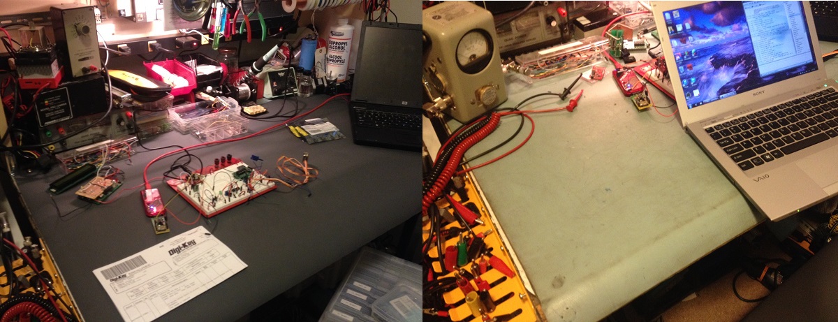
Okay, there is a LOT of test equipment out there for you to buy and you will need a lot of it as you take on projects. I have a bench full of test equipment, a bunch on shelving in the garage and I still have a running list of things I want to buy in the semi-near future.. my list:

HV Power Supply
Programmable Power Supply
Programmable Load
MSO Scope
Spectrum Analyzer
RF Signal Generator
Oscilloscope 4 Channel
Arbitrary Function Generator

I have a lot of older equipment, plenty of it was bough for one project and entirely inadequate for others, I also have a lot of ham radio equipment like a HP universal bridge, Bird Watt meter, etc, etc etc.. most of my “affordable” test equipment came from ham swaps and eBay.. ham radio clubs can be a great source for pairing up with people interested in electronics (just avoid the guys with lightbars and more than 3 antennas on their vehicles… trust me.. avoid them).

Oh and on a final note: Dear Tektronix/Fluke, I would will like some of your equipment … a lot of it in fact, used it good! I’m not too picky 🙂 I promise to show it off often and I live like 5 miles away from you.. I’ll pick it up!

TYMKRS Rotary Encoder + TAUTIC 20 Pin Dev Board PIC Test/Code

I got an order from Tindie last night. I had issues with my DIY stepper based rotary encoder so when I saw TYMKRS “Turn Me v1” kit I had no hesitation parting with $10. It seemed to only come with Arduino sample code so I wrote my own code. My code is written in assembly for the PIC because that’s my preferred microcontroller and I’m not much of a C programmer. I happened to get another pair of Jayson Tautic’s 20 Pin Development Boards. Check out his Tindie store.. he has a bunch of interesting things. If I still lived in the midwest I’d pick up that lightning detector. (Jayson, if you ever read this your fan’s request more awesomness)

These wasn’t a ton of sample code online … some 16F88 code I didn’t care for… 16F84 code that was wretched… and some interrupt driven code I wasn’t feeling either so I wrote my own polling code from scratch. It’s commented enough to get what I was doing. The schematic should be fairly obvious, not counting the LED resistors I used a pull down resistor on the switch built into the encoder.

To my knowledge, while writing the code, I had my very first stack overflow bug!

I received the rotary encoder yesterday and I had another pair of Tautic's 20 pin development boards show up the day before. The 20 pin dev board comes with a Microchip PIC 16F1509.
I received the rotary encoder yesterday and I had another pair of Tautic’s 20 pin development boards show up the day before. The 20 pin dev board comes with a Microchip PIC 16F1509.
A few pieces, this went together in a few moments. The unlabeled connector side of the board is just support.

The important stuff:

;*******************************************************************************
;   Rotary Encoder Test, 2 bit                                                                              *
;   http://www.iradan.com
;
;   RA0:    OUT     TEST LED
;   RA1:    IN      ENC_B INPUT, NOTE: DISCONNECT OR INSURE LOW WHEN PROGRAMMING
;   RA2:    IN      ENC_A INPUT
;   RB5:    OUT     SWITCH STATUS LED
;   RB7:    IN      SWITCH INPUT
;   RC<0:7> OUT     ENCODER "COUNT"
;
;   VERSION 0.1     INITIAL CODE
;
;*******************************************************************************

    errorlevel -230, -302, -303, -313
    LIST R=DEC

#include "p16f1509.inc"

    __CONFIG _CONFIG1, _FOSC_INTOSC & _WDTE_OFF & _PWRTE_ON & _CLKOUTEN_OFF
    __CONFIG _CONFIG2, _LVP_OFF & _STVREN_ON

            UDATA_SHR
COUNT       RES .1
ENC_LAST    RES .1
ENC_CURRENT RES .1

#DEFINE ENCA    PORTA,1
#DEFINE ENCB    PORTA,2
#DEFINE ENC_SA  ENC_LAST,0
#DEFINE ENC_SB  ENC_LAST,1
#DEFINE ENCA_NOW    ENC_CURRENT,0
#DEFINE ENCB_NOW    ENC_CURRENT,1

;*******************************************************************************
; Reset Vector
;*******************************************************************************

RES_VECT  CODE    0x0000            ; processor reset vector
    GOTO    START                   ; go to beginning of program

;*******************************************************************************
; MAIN PROGRAM
;*******************************************************************************

MAIN_PROG CODE                      ; let linker place main program

START
    CALL    INIT

    BANKSEL PORTA
    BSF     PORTA,0         ;THIS WAS FOR TESTING.

    GOTO    LOOP

INIT
    CLRF    COUNT

    BANKSEL PORTC
    CLRF    PORTC
    BANKSEL LATC            ;Data Latch
    CLRF LATC               ;
    BANKSEL ANSELC          ;
    CLRF ANSELC             ;Digital IO
    BANKSEL TRISC           ;
    MOVLW   B'00000000'     ;RC<0:7> OUT
    MOVWF   TRISC

    BANKSEL PORTA           ;
    CLRF PORTA              ;Init PORTA
    BANKSEL LATA            ;Data Latch
    CLRF LATA               ;
    BANKSEL ANSELA          ;
    CLRF ANSELA             ;digital I/O
    BANKSEL TRISA           ;
    MOVLW B'00111110'       ;Set RA<0,6:7>out RA<1:5> in
    MOVWF TRISA             ;

    BANKSEL TRISB
    MOVLW   B'11011111'     ;RB<5> OUT, RB<0:4>,<6:7> IN
    MOVWF   TRISB
    CLRF    PORTB

   BANKSEL OSCCON           ;SET OSCILLATOR SPEED
    MOVLW   0x78            ;01111000  / 16MHz
    MOVWF   OSCCON

    CLRF    ENC_CURRENT     ;HOUSE KEEPING
    CLRF    ENC_LAST

    RETURN

LED
    BANKSEL PORTB           ;THIS TURNS ON SWITCH STATUS LED
    BSF PORTB,5
    RETURN

INCR
    INCF    COUNT,f
;   GOTO    RESUME
    RETURN

DECR
    DECF    COUNT,f
;    GOTO    RESUME
    RETURN

DETERMINE_DIRA
    BTFSC   ENCB_NOW        ;OKAY WHICH WAY DID IT TURN?
    CALL    INCR            ;INCREMENT
    BTFSS   ENCB_NOW
    CALL    DECR            ;DECREMENT
    RETURN

TESTLASTA
    BTFSS   ENC_SA          ;SO ENCA WAS HIGH, WAS IT LAST TIME?
    CALL    DETERMINE_DIRA  ;YEP..
    NOP                     ;GUESS NOT, RETURNING
    RETURN

TEST_ENC                    ;I'M ONLY TESTING FOR A HIGH ON ENC A.
    BTFSC   ENCA_NOW        ;THAT MEANS EVERY OTHER TICK ON THE ENCODER
    CALL    TESTLASTA       ;DOES NOTHING
    RETURN

LOOP
    NOP

    BANKSEL PORTB
    BCF PORTB,5             ;TURN OFF SWITCH STATUS LED
    BANKSEL PORTA
    BTFSC   PORTA,5         ;TEST IF SWITCH IS PUSHED
    CALL    LED             ;BRANCH IF ON, SKIP IF NOT
    NOP

    BCF ENCA_NOW            ;CLEAR CONTENTS OF ENCODER "NOW BITS"
    BCF ENCB_NOW

    BANKSEL PORTA
    BTFSC   ENCA
    BSF     ENCA_NOW        ;ENC_A INPUT IS HIGH
    NOP
    BTFSC   ENCB
    BSF     ENCB_NOW        ;ENC_V INPUT IS HIGH

    CALL    TEST_ENC        ;TEST ENC_A

    BANKSEL PORTC           ;DUMP ENCODER COUNT ONTO PORTC
    MOVFW   COUNT
    MOVWF   PORTC

    BCF     ENC_SA          ;SAVE STATUS OF ENCODER A & B INPUTS
    BTFSC   ENCA_NOW
    BSF     ENC_SA

    BCF     ENC_SB
    BTFSC   ENCB_NOW
    BSF     ENC_SB

    BANKSEL PORTA           ;USED FOR TESTING
    BCF     PORTA,0

    GOTO LOOP               ;LOOP FOREVER

    END