I got a rando e-mail offering me “free parts” and I usually don’t even bother opening the e-mail. It’s ALWAYS garbage right? Well, maybe I hadn’t slept well the night before but I opened it. (psss. You can scroll down about a page before I actually get anywhere in this post…)
What was I thinking? I hovered carefully over the link… seemed pretty safe… short-ish domain ended with a .com .. not extra stuff on the end… OK. They got me. The website was http://digitspace.com — It seemed like an electronics website so I e-mailed. Back…. going back and forth they seem to be running some kind of promotion or perhaps they are trying to build some brand recognition getting bloggers to give them some advertising. In the end selected $50 worth of parts that consisted of two ESP32 micro dev boards that had WiFi (of course), LoRa, OLED display and and extra LED. There was some switch button types but they were a bit more and for some reason I didn’t think I needed them. Well a week later these things actually showed up (and I didn’t have to give them my credit card or paypal info!).
OK THE START..
A week later the boards showed up in the mail.. they look and feel reasonable and they came with some sample firmware that proved they worked. Unfortunately the site did not include any documentation… but I did the “hardwork” for you if you want to follow along… but let’s start with the end… So far I am here:
First thing first I had to add ESP32 support to my Arduino IDE.. I dropped this in the “additional board manager URLs”:
I found a simple tx-rx LoRa code off the internet but I won’t share because it took too much re-work to get working on my board. So I took it’s essience …
I had to add these libraries:
Add libraries: Adafruit SSD1306 by Adafruit Adafruit GFX Library by Adafruit LoRa by Sandeep Mistry
(all came right off the normal library manager)
I couldn’t find an OLED library that worked until reading some and found I liked this one that seemed to be the “best for me”: https://github.com/osresearch/esp32-ttgo
My findings were similar … though I haven’t ACCURATELY measured it my USB analyzer says 50mA on and 10mA off.. no peak readings yet but I can live with 10mA in my project.
By request one of my long lost blogs was a MODbus RTU application for a PIC 18F27J53. You could easily plop this onto many of the 18F series micros. It doesn’t do much but it’s a great stepping stone for throwing in your own IO. I’ll probably follow up with an Arduino version in a while.. I’ll put it on my “todo” list.
The code…
/*
 File:   main.c
 Author: Charles M Ihler
 Contact at: http://iradan.com
 *
 Created on November 8, 2014, 2:37 PM
 *
 Target Device:
 18F27J53 Development Board by AtomSoft
 *
 Project: MODbus/RTU slave
 *
 Notes
 We will ignore both query high bytes for now
 TODO:   Pull all hard coded IO out eventually and set it up via USB?
 Maybe a terminal application for enabling points?
 *
 *
 Version:
 0.02     Controlled sends caned reply on request to address on RS-232
 0.03     CRC works on RX
 0.04     No actual IO yet..
 Function 0x02 (Read Input Status) Started
 0.05     Ported to 18F17J53 for expanded IO/USB options.
 12MHz XTAL with CPUDIV set to 16MHz
 *
 / //#ifndef _XTAL_FREQ //#define _XTAL_FREQ 16000000 // //#define __delay_us(x) _delay((unsigned long)((x)(_XTAL_FREQ/4000000.0)))
 //#define __delay_ms(x) _delay((unsigned long)((x)*(_XTAL_FREQ/4000.0)))
 //#endif
 // PIC18F27J53 Configuration Bit Settings
 // 'C' source line config statements
 include
 // #pragma config statements should precede project file includes.
 // Use project enums instead of #define for ON and OFF.
 // CONFIG1L
 pragma config WDTEN = OFF      // Watchdog Timer (Disabled - Controlled by SWDTEN bit)
 pragma config PLLDIV = 3       // PLL Prescaler Selection (Divide by 3 (12 MHz oscillator input))
 pragma config CFGPLLEN = ON    // PLL Enable Configuration Bit (PLL Enabled)
 pragma config STVREN = ON      // Stack Overflow/Underflow Reset (Enabled)
 pragma config XINST = OFF       // Extended Instruction Set (Enabled)
 // CONFIG1H
 pragma config CPUDIV = OSC3_PLL3// CPU System Clock Postscaler (CPU system clock divide by 3 from 48MHz)
 pragma config CP0 = OFF        // Code Protect (Program memory is not code-protected)
 // CONFIG2L
 pragma config OSC = HSPLL      // Oscillator (HS+PLL, USB-HS+PLL)
 pragma config SOSCSEL = HIGH   // T1OSC/SOSC Power Selection Bits (High Power T1OSC/SOSC circuit selected)
 pragma config CLKOEC = OFF      // EC Clock Out Enable Bit  (CLKO output enabled on the RA6 pin)
 pragma config FCMEN = OFF      // Fail-Safe Clock Monitor (Disabled)
 pragma config IESO = OFF       // Internal External Oscillator Switch Over Mode (Disabled)
 define _XTAL_FREQ 16000000 //defined for delay
 char    ctxt[10], buf1, testcrc[4];    //buff serial string volatile unsigned int     ping, isrcall, index, reading, new_rx; int address, crc_high, crc_low, i, querylength; unsigned int result; //these variables are for fuctions to be enabled/disabled and pushed into application code via later int frame, z, bufferbits, query_reg_address, y; char data_out[64]; char reg_address[255];
 /*
  *
 Interrupt Service
 *
 UART RX and Timer 1
 *
 */
 void interrupt ISR() {
 if (PIR1bits.RCIF)          // see if interrupt caused by incoming data
 {
     isrcall = 0x01;
     char temp;
     temp = RCREG;     // read the incoming data
     buf1 = temp;
     if(temp==address && reading==0)      //if my address..
     {
         index = 0;                  //reset index
         reading = 1;                //from now on go to else if
         LATCbits.LATC1 = 1;
         new_rx = 0;
         ping = 1;
     }
     else if(reading == 1)           //in middle of GPS sentence
     {
         //TODO reset timeout timer
         ctxt[index] = temp;         //load it up
         index++;                    //increment index
         ping = 1;                   //this is for debugging
         if(index > 6)              //1+7 = master frame.
             {
             index = 0;              //reset index
             reading = 0;            //no longer storing the string
             new_rx = 1;             //"ding"
             T1CONbits.TMR1ON = 0;
             }
     }
 }
 //RCSTA2bits.FERR = 0;    //Clear errors
 //RCSTA2bits.OERR = 0;
 //time out timer, if tripped new_rx=0;
 if (PIR1bits.TMR1IF)
 {
     new_rx=0;
     ping = 0;
     T1CONbits.TMR1ON = 0;
     PIR1bits.TMR1IF = 0;
     if (reading) {
     reading = 0;
     LATCbits.LATC0 = 1;
     }
 }
 }
 void init_io(void) {
 INTCONbits.GIE = 0;         //no interruptions please ADCON0 = 0b00000000;        //don't need any ADC ADCON1 = 0b00000000;        //speed Vref=AVdd, VssRef=AVss LATA = 0x00; LATB = 0x00; LATC = 0x00; TRISAbits.TRISA0 = 1; // address 1 TRISAbits.TRISA1 = 1; // address 2 TRISAbits.TRISA2 = 1; // address 3 TRISAbits.TRISA3 = 0; // output TRISAbits.TRISA5 = 0; // output TRISBbits.TRISB0 = 0; // TRISBbits.TRISB1 = 1; // TRISBbits.TRISB2 = 0; // TRISBbits.TRISB3 = 0; // TRISBbits.TRISB4 = 0; //  TRISBbits.TRISB5 = 1; //  TRISBbits.TRISB6 = 0; //  TRISBbits.TRISB7 = 0; //  TRISCbits.TRISC0 = 0; // timer LED output TRISCbits.TRISC1 = 0; // output TRISCbits.TRISC2 = 0; // LED test output TRISCbits.TRISC3 = 0; // output //TRISCbits.TRISC4 = 1; // USB //TRISCbits.TRISC5 = 1; // USB TRISCbits.TRISC6 = 0; // output TX1 TRISCbits.TRISC7 = 1; // input  RX1
 }
 void __delay_10ms(unsigned char n)     //__delay functions built-in can't be used for much at this speed… so!
  {
      while (n-- != 0) {
          __delay_ms(10);
      }
  }
 void uart_xmit(unsigned int mydata_byte) {
 while(!TXSTAbits.TRMT);    // make sure buffer full bit is high before transmitting TXREG = mydata_byte;       // transmit data
 }
 void write_uart(const char txt) {                                 //this send a string to the TX buffer                                 //one character at a time        while(txt)
        uart_xmit(*txt++);
 }
 void serial_init(void)
 {
     //9600 8N1
 TXSTA1bits.SYNC = 0; TXSTA1bits.BRGH=1;       // select low speed Baud Rate (see baud rate calcs below) TXSTA1bits.TX9=0;        // select 8 data bits TXSTA1bits.TXEN = 1;     // enable transmit RCSTA1bits.SPEN=1;       // serial port is enabled RCSTA1bits.RX9=0;        // select 8 data bits RCSTA1bits.CREN=1;       // receive enabled SPBRG1=102; SPBRGH1=0; PIR1bits.RCIF=0;        // make sure receive interrupt flag is clear PIE1bits.RCIE=1;        // enable UART Receive interrupt INTCONbits.PEIE = 1;    // Enable peripheral interrupt INTCONbits.GIE = 1;     // enable global interrupt  __delay_10ms(5);        // give time for voltage levels on board to settle
 }
 void run_timer (void) {
     T1CONbits.TMR1ON = 0;
     TMR1=0;
     TMR1L=0x00;
     TMR1H=0xAA;
     T1CONbits.TMR1CS = 0x01;
     T1CONbits.T1CKPS = 0x01;
     PIE1bits.TMR1IE = 1;
     T1CONbits.TMR1ON = 1;
 //        PIR1bits.TMR1IF=0;
 }
 void check_my_address(void) {
     /*
      *  Determine what address the unit is based on DIP switches
      *  PORTAbits.RA0   Switch 1
      *  PORTAbits.RA1   Switch 2
     */
 if (PORTAbits.RA0 & PORTAbits.RA1) address = 0x04; if (!PORTAbits.RA0 & PORTAbits.RA1) address = 0x03; if (PORTAbits.RA0 & !PORTAbits.RA1) address = 0x02; if (!PORTAbits.RA0 & !PORTAbits.RA1) address = 0x01;
 }
 /*
 TODO
 Poll the inputs
 *
 I will probably use a 74138 to address banks with 74HC245 for byte/banks of inputs
 I will likely use the same set up for "Coils"
 For input registers (analog inputs) I will consider perhaps some kind of A/D input with CD4066+74HC138
 *
 */
 void poll_my_inputs(void) {
 //just stuff it with something for now for (z = 0; z < 64; ++z) { reg_address[z] = z; }
 }
 /*
 did the chicken come before the egg?
 this MODbus CRC bit was gently borrowed from the internet..
 I can't determine who wrote it.. it shows up in an Ardiuno Sketch for MODbus
 Modbus over serial line - RTU Slave Arduino Sketch
 with referenced of Juan Pablo Zometa, Samuel Marco, Andras Tucsni, Philip Costigan
 It also shows up on a number of websites and forums uncredited… many PIC or C based ..
 so who knows, but I didn't write it
 The MODbus CRC-16 function is outlined on the Modicon site for reference
 */
 unsigned int modbus_crc(unsigned char buf[], int start, int cnt)
 {
 int     i,j;
 unsigned temp, temp2, flag;
 temp=0xFFFF;
 for (i=start; i<cnt; i++){
    temp=temp ^ buf[i];
 for (j=1; j<=8; j++){       flag=temp & 0x0001;      temp=temp >> 1;
      if (flag) temp=temp ^ 0xA001;
      }
   }
 /*** Reverse byte order. ***/
 temp2=temp >> 8;
 temp= (temp << 8) | temp2;
 return(temp);
 }
 int check_master_crc (void) {
 int diff, diff1, diff2;       //what we send back char data[6]; result = 0x0000; crc_high = 0x00; crc_low = 0x00; data[0] = address;  //this is ugly but all master queries are 6bytes+CRC so it'll do data[1] = ctxt[0];  //function data[2] = ctxt[1];  //start_addressH data[3] = ctxt[2];  //start_addressL data[4] = ctxt[3];  //# of regH data[5] = ctxt[4];  //# of regL result = modbus_crc(data,0,6); crc_high = result >> 8; crc_low = result & 0x00FF; diff1 = ctxt[5] ^ crc_high; diff2 = ctxt[6] ^ crc_low; diff = diff1 + diff2; //this spits back an XORed value between calculated and received CRC return(diff);
 }
 void respond_input_status(void) {
         //ctxt[1] start_addressH
         //ctxt[2] start_addressL
         //ctxt[3] # of regH
         //ctxt[4] # of regL
     querylength = ctxt[4];  //ignoring upper byte for now (TODO)
     query_reg_address = ctxt[2]; //ignoring upper address byte (TODO)
 frame = 0;     //data frame counter do {     data_out[frame] = reg_address[query_reg_address];     //TODO  make this do somethng     querylength--;     frame++; } while (querylength>0); querylength = ctxt[4];  //reload so we can count time transmitting data result = modbus_crc(data_out,0,2); crc_high = result >> 8; crc_low = result & 0x00FF; //uart_xmit response address, function, data_out[frames], CRC uart_xmit(address); uart_xmit(ctxt[0]); frame = 0; do {     uart_xmit(data_out[frame]);     //TODO  make this do somethng     querylength--;     frame++; } while (querylength>0); uart_xmit(crc_high); uart_xmit(crc_low);
 }
 int main(void) {
     OSCCONbits.SCS = 0x00;
 new_rx=0; init_io(); serial_init(); run_timer(); check_my_address(); y += address; write_uart("MODBus "); uart_xmit(y); LATCbits.LATC0 = 1; LATCbits.LATC1 = 1; __delay_10ms(50); LATCbits.LATC0 = 0; LATCbits.LATC1 = 0; if (address == 0x01){     LATCbits.LATC0 = 1; } if (address == 0x02) {     LATCbits.LATC1 = 1; } __delay_10ms(50); LATCbits.LATC0 = 0; LATCbits.LATC1 = 0; INTCONbits.GIE = 1; INTCONbits.PEIE = 1; while (1) {     //If read data, not me and then if no 232 traffic for >800us then any xmit over     //104 us (9600) x 8 quiet periods minus some for wiggle.     if (ping) {         run_timer();     }     if (new_rx) {       //this device was polled         //testing response         i = check_master_crc();     //check master query crc         if (i==0x00) {              //CRC Ok?             if (ctxt[0] == 2) {       //coil status query                 respond_input_status();             }             //TODO other types of functions go here         }         //all done, get ready for new query         new_rx = 0;     }     //testcrc[0] = 0xFF;     //testcrc[1] = 0x02;      //right now this is only thing processed     //result = modbus_crc(testcrc,0,2);     //crc_high = result >> 8;     //crc_low = result & 0x00FF;     __delay_10ms(10);     LATCbits.LATC2 = 1; //LED blinky test     __delay_10ms(10);     LATCbits.LATC0 = 0;     LATCbits.LATC1 = 0;     LATCbits.LATC2 = 0; }
 }
Five years ago I had an itch to talk to other people; so overrated.
The End.
OK, fine.. I originally was thinking of some electronics club but after talking with a few people and refining my ideas through research, it was clear this idea fit best as a makerspace. I bought a meetup.com subscription. For as crappy as it is, Meetup does have a surprising network of members and access to kickstart your local community group. There is no question SnoCo Makerspace wouldn’t be if it wasn’t for Meetup. I set a meeting for a couple weeks out in a Lynnwood library and 35 people showed up. I gave these suckers my pitch… and I got back: “What’s your makerspace going to have in it?” … Of course I’d thought about what I wanted but I gave her the predictable answer along the lines of “OUR makerspace will have whatever interests the membership”. I had my own makerspace… at home, I was looking for something social.
That leads me to my first suggestion*: 1. The only successful reason for starting a makerspace should be social. If your core members don’t evolve fairly quickly into friends you’re not going to make it, prove me wrong.
We avoided a couple misteps in attempting, but failing, to start out at a local college (avoid at all costs), a port authority and later on another college. Outside of finding someone with really-free space, you’re going to have to figure out how to do it on your own. Don’t rely on any entity unless you have the check in your hand but it’s fairly rare to find free-money. If you don’t believe me pop onto the Nation of Makers facebook group and ask the question… NOM is kind of a lobbying group for makerspaces but they don’t really do anything outside run a convention. It had a purpose? There is a little history there if you’re bored and want to look it up.
Our first space; the only thing we found that worked. We found a small space in a space designed for micro-businesses. It was enough for 10 core members and visitors to use a laser cutter, 3D printer, and an electronics lab. This was a good bootstrap project and I ended up fronting most of the money for the lease outside a couple generous large checks when we started. Costs were offset by 10-15 members dues ($40, with the understanding we knew we weren’t work it but build it and they will come). Once we started workshops the space broke even.
Which brings me to tip #2: Don’t start a makerspace unless you already own many of the tools or know someone you can borrow them from. I’m talking core tools… they don’t have to be the best… just usable and safe, bonus points for aesthetically pleasing.
The adventure is a series of leaps of faith moments, scares, disappointments, and elation to success. You should have some business sense, avoid cliques but allow for them, be likable to most, don’t talk poorly of anyone, be positive and strive to inspire… above most take care of your toxic members, one or two can ruin your group and the experience of anyone coming through the door for a first peek. Make sure you have someone with a positive attitude greet and talk to every single person who comes through the door. Ask them questions to include what they’re interested in and what they expected.
Chas performing the ribbon cutting at SnoCo Makerspace new location
Our Makerspace 2.0 came out of space necessity. It would have been nice to be “in Seattle” but outside SoDo nothing had/has survived being in Seattle. It’s too expensive. We chose to move a few miles north of Lynnwood because space was cheaper, available, and Everett is a manufacturing town. Located 23 miles north of Seattle the makerspace pulls people in who live in North Seattle, Bellevue and north. The rent in Everett is affordable and for most of our existence outside the first few months of start-up and a “big leap” the space has been sustainable through membership and workshop income.
Okay.. so what sucked?
Time. I spent more time on on this makerspace in the beginning than my 40-hour/week job. It tapered off a little here and there but finding that core group to help.
Workshops. Finding people to teach courses… that can teach. I recommend creating a workshop template and guide… ask them to help you create hand-outs and documents for reoccurring workshops. It’ll help multiple people teach the same thing, the won’t forget important items like safety.. and there will be perceived value from attendees. Even when you pay people or credit dues… e-mails blasts will get the attention of a few people willing to teach: you should corner people and get a commitment with a date. If you don’t have workshops you probably will not succeed. People want to learn.. we have plenty of people who take workshops but never even use the tool… they just wanted to know how. Most of our attendees aren’t even members.
Money. So much out of pocket cash.. particularly if you have to buy tools first. (Pro-tip #3. Tool-drives are nice…but be prepared to make a goodwill drop off when you’re done.. you get a lot of garbage with the occasional gems) .. I don’t know how many thousands of dollars I’ve spent over four years.. I don’t even want to calculate it roughly. Well in excess of $20k… probably a few times that. If you find big donors or business sponsors… well buy lotto tickets. No one gives away money… we have a couple companies that match but matching and donations make up less than 5% of our income.
Space. What a pain… It takes forever to find a space.. then if it’s not close enough to usable you have to do some construction.. and decide if you’re going to do it legit or shady-maker-style. I tried for months working with city and county government entities to find low cost options… oddly Everett does give away very cheap rent in one of there buildings to some non-profit that is kind of a consignment shop for “makers”… mostly knitted stuff, books, jam, etc.. they didn’t have any interest in discussing possibilities with me but it’s good to have the contacts anyways. Doesn’t hurt to try, maybe you’ll get lucky.
Insurance. Originally it took WEEKS of calling to find an insurance broker who could find a company to insure us. Over time we found another company, and then a company recommended an agent that did pick us up for a little more money but more flexibility. I never did find a company that would allow a minor to touch anything… I recommend selling your makerspace as very similar to some kind of industry or education center. Stick to selling yourself as a CBO to donors and such. You’ll find issues finding insurance companies that will let you play with real toys if you are a “club”, but don’t lie.. or you might as well not even have insurance.
Tip #4. Don’t start a makerspace if you think you’re going to make an income at it. Eventually you’re hire someone which is as big step, but no one on your board is going to want to pay that person what they’re worth when they’ve been donating all that time. Your first hire will likely be half-book keeper because that seems to be about 1/2 of the reoccurring work once you’re stable and of first-hire size.
What didn’t suck?
I don’t regret starting the makerspace, I wouldn’t do it again and I am pretty sure I wouldn’t have done it if I knew what I know now.. but I am glad I did and it was worth it. I’ve done plenty of volunteer work before, if I hadn’t I suspect I’d feel more fulfilled in that regard. I created (with A LOT of help) a wonderful organization that is inclusive and provides a ton of social interaction, mentoring, and support to our members, guests, and community (we do some out reach… fix 3d printers for schools, etc.). There are a couple really enriching moments over the last few years… the best part is many of my now-closest friends I met in the makerspace… so that itch to talk to people was thankfully fulfilled.
My Cred: I founded the largest** makerspace in Washington State; I’ve helped consult start-up three other spaces, inspired others and seen dozens fail, most of them before they really got started. **We have a commercial fab lab which is larger but it’s really a commercial fab business, they have more sq ft.. Largest as measured by membership and presumed participation.
*In no way should this reflect any kind of government ran/funded makerspace to include schools, city government, museum spaces, art council funded space, etc. Additionally I do not consider incubators or co-working spaces to be makerspaces.
I took a hiatus from blogging for a few years. I decided it’d be clever to start a makerspace. https://snocomakers.org … yeah it worked out but wow I really have to recommend avoiding any part of running a makerspace if you want to have time to do anything else, at all. I didn’t do any lawn work in 2018.. that did not make the wife happy.
In late 2018 I claimed makerspace success. It was a proper makerspace with all the required tools and more and was the largest organization in the state. I decided it was time to step down and let some other folks shape it. So.. I guess, here I am again? I’ll probably drop my hot tips and tricks for starting up a makerspace in a couple weeks.
So on to this missing content business: Short-story-long, I created a cloudy service for access control on doors & equipment which I thought I’d monetize but decided against… however while creating it I moved my hosting package over to an upgraded account. Somehow in the process I lost my backup of this blog… ARG! The last one I had was from late 2014. I know I had a newer one but the backups were on my dead Yoga. So… sorry for all that good stuff missing… oh well. I will probably drop all my code for the cloudy based access control system in the future. It’s in php server side and python on a rpi zero at the reader… nice and cheap. p.s. I dislike Python. It was my first python project, it’ll be my last. Kudos to you if you’re a fan… I think you’re <TAB>insane.
If you showed up here on a 404 and hope to score something I had before I did capture all my media in an FTP upload.. let me know what you’re looking for and I’ll hook you up.
I sat at the bench this morning waiting for the inspiration to continue on with a project I’m working on with Francesco; I gave in to procrastination.
I wrote some assembler code to generate WWVB signal from a PIC a few months ago, remember? That stirred some interest from overseas folks looking for a way for their automatically update their “atomic” watches… apparently there isn’t some NTP device or anything else easily found to be purchased to do this. I was asked to do this NTP, but I’ll leave that for someone with a ‘Pi–I gave mine away to a kid. I did this project using GPS and a PIC micro.
It’s a pretty simple setup, gobble up a GPRMC sentence, pick off the data I need and spit out time. I generate 60KHz with the PWM module within the PIC (okay it’s 62KHz, but that should be close enough).. switch it through a 4066 to generate my time code.
GPRMC: there are other sentences you can use, but my cheapo module only spits out 4 sentences and GPRMC is the only one with time and date, so it’ll do. I re-used my GPGGA parsing code.. there is probably some left-overs in there if you look at the code below. I also dump the working string (first 63 bits of GPGGA) followed by the day number of the year which is calculated on the the UART, pick it up off the TX line @ 9,600 baud.. It’s spits it out about once a minute (in between time transmissions). I ended up using some DOY code online because I found some nice code that included determining if it was a leap year for day-of-year determination; I left the URL in the code.
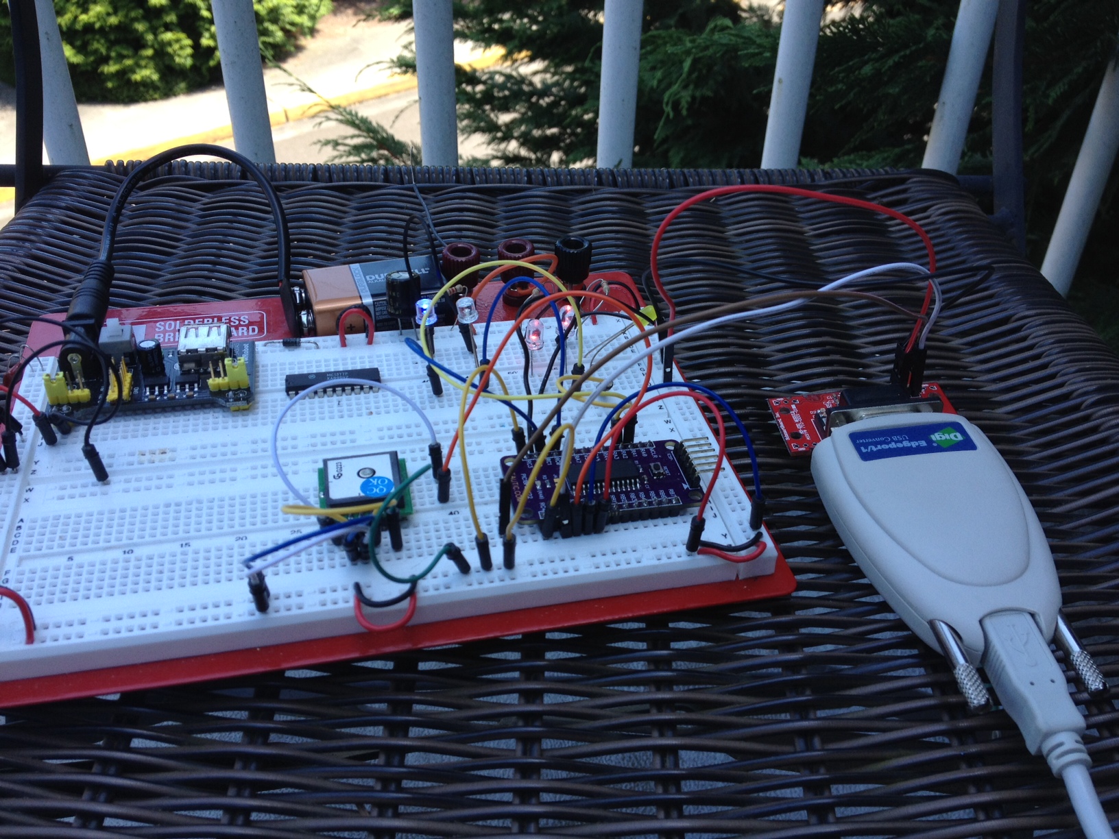
The code isn’t finished nor is it accurate: it doesn’t recognize the valid data bit yet, and just spits out time whenever it feels like it so the time can be off by up to 59 seconds. I’ll work on this later on since I was just looking for proof of concept so I could get the hardware going and off a breadboard. I built up the circuit in eagle.. I’ll check it a few more times and have a couple PCBs made for round one of testing. The prototype was built on a Tautic 18F26K22 dev board, I considered just having the dev board plug-in but that’s probably a waste of $$.
You’ll note the SMA jack, perhaps this is over kill since I’ll never have a good enough antenna to match 60KHz… I don’t really know what to do with that yet, wire antenna for now I suppose. (version 2?) It’s likely illegal to sell these since it’s purposefully broadcasting, fat chance I’m doing the research beyond the FCC. I’ll look it up tomorrow but I suspect Part 15 doesn’t apply to 60KHz.
Version 1 of the GPS>WWVB board
The code is a total hack job.. poorly documented, perhaps even incorrectly documented. I know I have “place-holder” functions.. but like I said.. it was a start to get my time code and it was close enough for testing; you get what you pay for! 🙂
/*
* File: main.c
* Author: Charles M Douvier
* Contact at: http://iradan.com / 0xEE.net / @chasxmd
* Created on April 4th, 2014
*
* Target Device: 18F26K22
*
* Project: GPS --> WWVB simulator
*
* This version uses the GPRMC block
* This is a limitation because GPRMC doesn't pass seconds
* The time passed will always be up to 60 seconds off
* I have to deterine DDMMYY --> Day of year, year
* No simple leap year info in GPS :(
*
* TODO
* Determine GPS lock and output to LED
* Consider re-writing how I am writing my time code
*
* I'll re-write this sometime with a better (more expensive) GPS module.
*
* Version:
* 0.1 First build I could prove I had GPS lock
* 0.2 Output time/date on 232
*
*/
#ifndef _XTAL_FREQ
#define _XTAL_FREQ 8000000 //4Mhz FRC internal osc
#define __delay_us(x) _delay((unsigned long)((x)*(_XTAL_FREQ/4000000.0)))
#define __delay_ms(x) _delay((unsigned long)((x)*(_XTAL_FREQ/4000.0)))
#endif
#include
#include
#include
#include
//config bits
#pragma config FOSC=INTIO67, WDTEN=OFF, PWRTEN=OFF, CP0=OFF, CP1=OFF, BOREN=ON
#pragma config STVREN=ON, LVP=OFF, HFOFST=OFF, IESO=OFF, FCMEN=OFF
//WRT=OFF, FOSC=INTOSC, MCLRE=ON
#define _XTAL_FREQ 8000000 //defined for delay
char ctxt[120], wstr[120]; //buff NMEA string, working string
char str1[20], str2[20], c, latstr, lonstr, setstr, doych[8];
char hourch[3], minch[3], secch[3], daych[3], monthch[3], yearch[3];
char buffer[32] = "none"; //temp dump
volatile unsigned int ping, isrcall, index, reading, new_rx;
int ready, gpgga, gprmc, mode; //gps associated vars
int leap_year, dayint, monthint, yearint, year4int, secondint, minuteint, hourint;
long doy;
int min_40, min_20, min_10, min_8, min_4, min_2, min_1;
int hour_20, hour_10, hour_8, hour_4, hour_2, hour_1;
int doy_200, doy_100, doy_80, doy_40, doy_20, doy_10;
int doy_8, doy_4, doy_2, doy_1, leapint;
int year_80, year_40, year_20, year_10, year_8, year_4, year_2, year_1;
//char *rxdata;
//volatile unsigned int uart_data; // use 'volatile' qualifer as this is changed in ISR
/*
* Interrupt Service
*/
void interrupt ISR() {
if (PIR1bits.RCIF){ // see if interrupt caused by incoming data
isrcall = 0x01;
char temp;
temp = RCREG1; // read the incoming data
if(temp=='$' && new_rx==0) //if first char of a GPS string..
{
index = 0; //reset index
reading = 1; //from now on go to else if
}
else if(reading == 1) //in middle of GPS sentence
{
ctxt[index] = temp; //load it up
index++; //increment index
ping = 1; //this is for debugging
if(index > 63) //thats more than enough data
{
index = 0; //reset index
reading = 0; //no longer storing the string
new_rx = 1; //"ding"
}
}
}
}
/*
* Set up my ports
*/
void init_io(void) {
// This code before the TRIS setup is for switching the RX2/TX2 to proper pins for the dev board
INTCONbits.GIE = 0; //no interruptions please
LATA = 0x00;
TRISAbits.TRISA0 = 0; //Onboard LED
TRISAbits.TRISA1 = 0; //LED
TRISAbits.TRISA2 = 0; //MCU (ON)
TRISAbits.TRISA3 = 1; // input
TRISAbits.TRISA4 = 1; // input
TRISAbits.TRISA5 = 1; // input
TRISAbits.TRISA6 = 1; // input
TRISAbits.TRISA7 = 1; // input
TRISBbits.TRISB0 = 0; // output
TRISBbits.TRISB1 = 0; // output
TRISBbits.TRISB2 = 0; // PWM1B
TRISBbits.TRISB3 = 0; // output
TRISBbits.TRISB4 = 0; // SCK
TRISBbits.TRISB5 = 0; // PWM1C
TRISBbits.TRISB6 = 0; // SCK
TRISBbits.TRISB7 = 1; // input
LATC = 0x00;
TRISCbits.TRISC0 = 0; // N/W
TRISCbits.TRISC1 = 0; // S/E
TRISCbits.TRISC2 = 0; // PWM1A (output to 4066 control)
TRISCbits.TRISC3 = 1; // MODE SELECT (LAT/LONG)
TRISCbits.TRISC4 = 1; // SET INPUT
TRISCbits.TRISC5 = 1; // input
TRISCbits.TRISC6 = 1; // input
TRISCbits.TRISC7 = 1; // input
ADCON0 = 0b00000000; //don't need any ADC
ADCON1 = 0b00000000; //speed Vref=AVdd, VssRef=AVss
ANSELA = 0x00;
ANSELB = 0x00;
ANSELC = 0x00;
}
void uart_xmit(unsigned int mydata_byte) { //send a character to the UART
while(!TXSTA1bits.TRMT); // make sure buffer full bit is high before transmitting
TXREG1 = mydata_byte; // transmit data
}
void uart_write(const char *txt) //sent a multiple characters
{
while(*txt != 0) uart_xmit(*txt++); //this send a string to the TX buffer
//one character at a time
}
void serial_init(void)
{
//9600 8N1
TXSTA1bits.BRGH=1; // select low speed Baud Rate
TXSTA1bits.TX9=0; // select 8 data bits
TXSTA1bits.TXEN = 1; // enable transmit
RCSTA1bits.SPEN=1; // serial port is enabled
RCSTA1bits.RX9=0; // select 8 data bits
RCSTA1bits.CREN=1; // receive enabled
SPBRG1=51; // here is calculated value of SPBRGH and SPBRGL
SPBRGH1=0;
PIR1bits.RCIF=0; // make sure receive interrupt flag is clear
__delay_ms(50); // give time for voltage levels on board to settle
uart_write("RESET"); // transmit some data for testing
}
void pwm_init(){
//
//Take care if setting up the PWM pins (DISBALE A/D, etc)
//
//Select the 8-bit TimerX resource, (Timer2,Timer4 or Timer6) to be used for PWM generation
//by setting the CxTSEL bits in the CCPTMRSx register.(1)
//
//Load the PRx register for the selected TimerX with the PWM period value.
//
//Configure the CCP module for the PWM mode by loading the CCPxCON register with the
//appropriate values.
//
//Load the CCPRxL register and the DCxB bits of the CCPxCON register, with the PWM
//duty cycle value.
//
// CCPR1L = 0x120;
CCPR1Lbits.CCPR1L = 0x01; //PWM duty cycle
//CCPR2Lbits.CCPR2L = 0xCE; //PWM duty cycle
//CCPR3Lbits.CCPR3L = 0xCE; //PWM duty cycle
PR2 = 0x01; //Timer 2 Prescale
//PR4 = 0xFF; //Timer 4 Prescale
//PR6 = 0xFF; //Timer 6 Prescale
CCPTMRS0bits.C1TSEL = 0x00; //PWM1 TMR2 Selection
//CCPTMRS0bits.C2TSEL = 0x01; //PWM2 TMR4 Selection
//CCPTMRS0bits.C3TSEL = 0x02; //PWM3 TMR6 Selection
CCP1CONbits.P1M = 0x00; //single output mode
CCP1CONbits.DC1B = 0x00;
PWM1CONbits.P1RSEN = 0;
PWM1CONbits.P1DC = 0x00; //dead band delay
ECCP1ASbits.CCP1AS = 0x00;
ECCP1ASbits.CCP1ASE = 0; //Auto-shutdown off
CCP1CONbits.CCP1M = 0x0C; //PWM Mode
//CCP2CONbits.CCP2M = 0x0C; //PWM Mode
//CCP3CONbits.CCP3M = 0x0C; //PWM Mode
PSTR1CONbits.STR1A = 1;
PSTR1CONbits.STR1B = 1;
//T2CONbits.T2OUTPS = 0x0F; //post scaler
T2CONbits.T2CKPS = 2; //16x prescaler
//T4CONbits.T4CKPS = 2;
//T6CONbits.T6CKPS = 2;
T2CONbits.TMR2ON = 1; //Turn the Timers On...
//T4CONbits.TMR4ON = 1;
//T6CONbits.TMR6ON = 1;
}
/*
* Append a string with a character
* append(str, c);
*/
//taken from http://stackoverflow.com/questions/19377396/c-get-day-of-year-from-date
int yisleap(int year)
{
return (year % 4 == 0 && year % 100 != 0);
}
int get_yday(int mon, int day, int year)
//use: int day = get_yday(1, 31, 2013);
{
static const int days[2][13] = {
{0, 0, 31, 59, 90, 120, 151, 181, 212, 243, 273, 304, 334},
{0, 0, 31, 60, 91, 121, 152, 182, 213, 244, 274, 305, 335}
};
int leap = yisleap(year);
leapint = leap;
return days[leap][mon] + day;
}
void append(char* s, char c)
{
int len = strlen(s);
s[len] = c;
s[len+1] = '\0';
}
void marker(void){
//send a marker frame - 800ms off, 200 ms on
LATBbits.LATB0 = 0;
__delay_ms(50);
__delay_ms(50);
__delay_ms(50);
__delay_ms(50);
__delay_ms(50);
__delay_ms(50);
__delay_ms(50);
__delay_ms(50);
__delay_ms(50);
__delay_ms(50);
__delay_ms(50);
__delay_ms(50);
__delay_ms(50);
__delay_ms(50);
__delay_ms(50);
__delay_ms(50);
LATBbits.LATB0 = 1;
__delay_ms(50);
__delay_ms(50);
__delay_ms(50);
__delay_ms(50);
LATBbits.LATB0 = 0;
}
void one(void){
//send a one - 500 ms off, 500 ms on
LATBbits.LATB0 = 0;
__delay_ms(50);
__delay_ms(50);
__delay_ms(50);
__delay_ms(50);
__delay_ms(50);
__delay_ms(50);
__delay_ms(50);
__delay_ms(50);
__delay_ms(50);
__delay_ms(50);
LATBbits.LATB0 = 1;
__delay_ms(50);
__delay_ms(50);
__delay_ms(50);
__delay_ms(50);
__delay_ms(50);
__delay_ms(50);
__delay_ms(50);
__delay_ms(50);
__delay_ms(50);
__delay_ms(50);
}
void zero(void){
//send a zero - 200ms off, 800ms on
LATBbits.LATB0 = 0;
__delay_ms(50);
__delay_ms(50);
__delay_ms(50);
__delay_ms(50);
LATBbits.LATB0 = 1;
__delay_ms(50);
__delay_ms(50);
__delay_ms(50);
__delay_ms(50);
__delay_ms(50);
__delay_ms(50);
__delay_ms(50);
__delay_ms(50);
__delay_ms(50);
__delay_ms(50);
__delay_ms(50);
__delay_ms(50);
__delay_ms(50);
__delay_ms(50);
__delay_ms(50);
__delay_ms(50);
}
void sendtime(void){
/*
*;0
xCALL MARKER ;MARKER FRAME REFERENCE BIT
xCALL ONE ;40min
xCALL ZERO ;20min
xCALL ZERO ;10min
xCALL ZERO ;Reserved
xCALL ZERO ;8mins
xCALL ZERO ;4mins
xCALL ONE ;2mins
xCALL ZERO ;1mins
xCALL MARKER ;MARKER 1
*/
marker(); //marker, frame reference
if (minuteint >= 40){ //40min
minuteint = minuteint - 40;
one();
}else {
zero();
}
if (minuteint >= 20){ //20min
minuteint = minuteint - 20;
one();
}else {
zero();
}
if (minuteint >= 10){ //10min
minuteint = minuteint - 10;
one();
}else {
zero();
}
zero(); //reserved (zero)
if (minuteint >= 8){ //8min
minuteint = minuteint - 8;
one();
}else {
zero();
}
if (minuteint >= 4){ //4min
minuteint = minuteint - 4;
one();
}else {
zero();
}
if (minuteint >= 2){ //2min
minuteint = minuteint - 2;
one();
}else {
zero();
}
if (minuteint >= 1){ //1min
minuteint = minuteint - 1;
one();
}else {
zero();
}
marker(); //marker 1
/*
;10
xCALL ZERO ;RESERVED
xCALL ZERO ;RESERVED
xCALL ZERO ;20hours
CALL ZERO ;10hours
CALL ZERO ;RESERVED
CALL ZERO ;8hours
CALL ONE ;4hours
CALL ONE ;2hours
CALL ZERO ;1hour
CALL MARKER ;MARKER 2
*/
zero(); //reserved
zero(); //reserved
if (hourint >= 20){ //20 hours
hourint = hourint - 20;
one();
}else {
zero();
}
if (hourint >= 10){ //10 hours
hourint = hourint - 10;
one();
}else {
zero();
}
zero(); //reserved
if (hourint >= 8){ //8 hours
hourint = hourint - 8;
one();
}else {
zero();
}
if (hourint >= 4){ //4 hours
hourint = hourint - 4;
one();
}else {
zero();
}
if (hourint >= 2){ //2 hours
hourint = hourint - 2;
one();
}else {
zero();
}
if (hourint >= 1){ //1 hours
hourint = hourint - 1;
one();
}else {
zero();
}
marker(); //marker 2
/*
*
;20
CALL ZERO ;RESERVED
CALL ZERO ;RESERVED
CALL ZERO ;200 day of year
CALL ONE ;100 day of year
CALL ZERO ;RESERVED
CALL ZERO ;80 day of year
CALL ONE ;40 day of year
CALL ZERO ;20 day of year
CALL ONE ;10 day of year
CALL MARKER ;MARKER 3
*/
zero(); //reserved
zero(); //reserved
if (doy >= 200){ //200th day
doy = doy - 200;
one();
}else {
zero();
}
if (doy >= 100){ //100th day
doy = doy - 100;
one();
}else {
zero();
}
zero(); //reserved
if (doy >= 80){ //80th day
doy = doy - 80;
one();
}else {
zero();
}
if (doy >= 40){ //40th day
doy = doy - 40;
one();
}else {
zero();
}
if (doy >= 20){ //20th day
doy = doy - 20;
one();
}else {
zero();
}
if (doy >= 10){ //10th day
doy = doy - 10;
one();
}else {
zero();
}
marker(); //marker 3
/*
;30
CALL ONE ;8 day of year
CALL ZERO ;4 day of year
CALL ZERO ;2 day of year
CALL ZERO ;1 day of year
CALL ZERO ;RESERVED
CALL ZERO ;RESERVED
CALL ZERO ;UTI Sign +
CALL ZERO ;UTI Sign -
CALL ZERO ;UTI Sign +
CALL MARKER ;MARKER 4
*/
if (doy >= 8){ //8th day
doy = doy - 8;
one();
}else {
zero();
}
if (doy >= 4){ //4th day
doy = doy - 4;
one();
}else {
zero();
}
if (doy >= 2){ //2nd day
doy = doy - 2;
one();
}else {
zero();
}
if (doy >= 1){ //1st day
doy = doy - 1;
one();
}else {
zero();
}
zero(); //reserved
zero(); //reserved
zero(); //reserved
zero(); //reserved
zero(); //reserved
marker(); //marker 4
/*
;40
CALL ZERO ;UTI Corr 0.8s
CALL ZERO ;UTI Corr 0.4s
CALL ZERO ;UTI Corr 0.2s
CALL ZERO ;UTI Corr 0.1s
CALL ZERO ;RESERVED
CALL ZERO ;80 year yearint
CALL ZERO ;40 year
CALL ZERO ;20 year
CALL ONE ;10 year
CALL MARKER ;MARKER 5
*/
zero(); //reserved
zero(); //reserved
zero(); //reserved
zero(); //reserved
zero(); //reserved
if (yearint >= 80){ //80th year
yearint = yearint - 80;
one();
}else {
zero();
}
if (yearint >= 40){ //40th year
yearint = yearint - 40;
one();
}else {
zero();
}
if (yearint >= 20){ //20th year
yearint = yearint - 20;
one();
}else {
zero();
}
if (yearint >= 10){ //10th year
yearint = yearint - 10;
one();
}else {
zero();
}
marker(); //marker 5
/*
*
;50
CALL ZERO ;8 year
CALL ONE ;4 year
CALL ONE ;2 year
CALL ZERO ;1 year
CALL ZERO ;RESERVED
CALL ZERO ;LEAP YEAR TRUE
CALL ZERO ;LEAP SEC WARN
CALL ONE ;DST
CALL ONE ;DST
CALL MARKER ;FRAME BIT P0
*
*/
if (yearint >= 8){ //8th year
yearint = yearint - 8;
one();
}else {
zero();
}
if (yearint >= 4){ //4th day
yearint = yearint - 4;
one();
}else {
zero();
}
if (yearint >= 2){ //2nd day
yearint = yearint - 2;
one();
}else {
zero();
}
if (yearint >= 1){ //1st day
yearint = yearint - 1;
one();
}else {
zero();
}
zero(); //reserved
//leap year
if (leapint){
one();
}else {
zero();
}
zero();
zero(); //leap sec warn
zero(); //dst??
zero(); //dst
marker(); //frame bit P0
}
void gettime(void){
hourch[0] = wstr[6]; //HHMMSS
hourch[1] = wstr[7];
minch[0] = wstr[8];
minch[1] = wstr[9];
secch[0] = wstr[10];
secch[1] = wstr[11];
daych[0] = wstr[56]; //DAY1 DDMMYY
daych[1] = wstr[57]; //DAY2
monthch[0] = wstr[58]; //MONTH1
monthch[1] = wstr[59]; //MONTH2
yearch[0] = wstr[60]; //YEAR1
yearch[1] = wstr[61]; //YEAR2
uart_write(wstr);
uart_write(" ");
hourint = atoi(hourch);
minuteint = atoi(minch);
secondint= atoi(secch);
dayint = atoi(daych);
monthint = atoi(monthch);
yearint = atoi(yearch);
year4int = yearint + 2000;
doy = get_yday(monthint, dayint, yearint);
ltoa(doych,doy,10);
uart_write(doych);
uart_write("\r");
}
void lon(void){
}
void determine_mode(void){ //determine lat or long mode
}
int main(void) {
// set up oscillator control register, using internal OSC at 8MHz.
OSCCONbits.IRCF = 0x06; //set OSCCON IRCF bits to select OSC frequency 8MHz
OSCCONbits.SCS = 0x02; //set the SCS bits to select internal oscillator block
__delay_ms(70); //lets think about life a bit before proceeding..
__delay_ms(70);
__delay_ms(70);
ping = 0;
new_rx = 0;
isrcall = 0;
init_io();
serial_init();
//RCONbits.IPEN = 0;
PIE1bits.RC1IE = 1; //Enable RX Interrupt
INTCONbits.PEIE = 1; // Enable peripheral interrupt
INTCONbits.GIE = 1; // enable global interrupt
pwm_init();
ready = 0;
while (1) {
__delay_ms(10);
isrcall = 0;
ping = 0;
if (ready){
LATCbits.LATC2 = 1;
}
if (new_rx == 1) //got our string...
{
if (strstr(ctxt, "GPRMC")) // && ready
{
gprmc = 1;
strncpy((char*)wstr, (char*)ctxt, sizeof(ctxt));
gettime();
}
new_rx=0; //finished with GPS string
}
if (gprmc){
sendtime();
}
gpgga = 0;
gprmc = 0;
}
}
I was asked to create a box that notified by LED if you were too far off a N/S or E/W course. I failed, I doubted the specified GPS accuracy/drift as my Garmin seems to stay pretty steady.. perhaps that’s some integration in the processing?
I started with one of the 18F26K22 TAUTIC development boards I bought from him off Tindie; They’re nice little breadboarding microcontrollers… I’ve recommended them before. I had purchased some GPS modules I got from eBay, so check .. they all have TTL NMEA output, some with 1PPS… and finally some tidbits I picked up out of my parts collection. Wrote some code.. tested it and found my drifting issue. After pondering the number 42 a while, I decided there was no sense in continuing because every idea I had meant something in the specification of the project was out.
I’m not going to go deep into explanation of the code since the project didn’t work but like all failures I learned something. I also expanded my knowledge of XC8 which was nice.. I’ve actively been coding in XC8 for a few months now; in some ways I miss ASM but XC8 does shorten the development time (if you don’t count how long it takes me to figure out atol() should have been used instead of atoi().
This project will be converted into a piece of test equipment of sorts. I’ve been meaning to hook a GPS receiver up to my WWVB transmitter and check it out. Of course WWVB is way more accurate … but if you can’t receive WWVB .. you’re up a creek.
GPS Receiver and Microcontroller outside locked.
Keep in mind this code is un-optimized, and essentially abandoned while I was building the framework. I leave it to you in case you want a jump start on grabbing some data out of a NMEA string.
/*
/*
 * File:   main.c
 * Author: Charles M Douvier
 * Contact at: http://iradan.com / 0xEE.net / @chasxmd
 * Created on April 4th, 2014
 *
 * Target Device: TAUTIC.com dev board / 18F26K22
 *
 * Project: AG GPS Indicator
 * Using a PIC to indicate if you're staying in lat/long "groove" by GPS.
 * *** This is not complete ***
 *
 *
 * Version:
 * 0.1      First build I could prove I had GPS lock
 * 0.2      Output GPS on 232 and position set, no debounce, etc.. abandonded
 */
#ifndef _XTAL_FREQ
#define _XTAL_FREQ 4000000 //4Mhz FRC internal osc
#define __delay_us(x) _delay((unsigned long)((x)*(_XTAL_FREQ/4000000.0)))
#define __delay_ms(x) _delay((unsigned long)((x)*(_XTAL_FREQ/4000.0)))
#endif

#include
#include
#include
#include


//config bits
#pragma config FOSC=INTIO67, WDTEN=OFF, PWRTEN=OFF, CP0=OFF, CP1=OFF, BOREN=ON
#pragma config STVREN=ON, LVP=OFF, HFOFST=OFF, IESO=OFF, FCMEN=OFF

//WRT=OFF, FOSC=INTOSC, MCLRE=ON

#define _XTAL_FREQ 4000000 //defined for delay

    char    ctxt[120], wstr[120];            //buff NMEA string, working string
    char    str[60], c, latstr, lonstr, setstr;
    char buffer[32] = "none";                        //temp dump
    volatile unsigned int     ping, isrcall, index, reading, new_rx;
    int     ready, gpgga, gprmc, mode;        //gps associated vars
    long long    position_set, position_now;
    //char    *rxdata;
    //volatile unsigned int uart_data;    // use 'volatile' qualifer as this is changed in ISR

/*
 *  Interrupt Service
 */
void interrupt ISR() {

   if (PIR1bits.RCIF){          // see if interrupt caused by incoming data

        isrcall = 0x01;
        char temp;
        temp = RCREG1;     // read the incoming data
        if(temp=='$' && new_rx==0)      //if first char of a GPS string..
        {
            index = 0;                  //reset index
            reading = 1;                //from now on go to else if
        }
        else if(reading == 1)           //in middle of GPS sentence
        {
            ctxt[index] = temp;         //load it up
            index++;                    //increment index
            ping = 1;                   //this is for debugging
            if(index > 50)              //thats more than enough data
                {
                index = 0;              //reset index
                reading = 0;            //no longer storing the string
                new_rx = 1;             //"ding"
                }
        }


   }
}


/*
 * Set up my ports
 */
void init_io(void) {

    INTCONbits.GIE = 0;         //no interruptions please

    LATA = 0x00;

    TRISAbits.TRISA0 = 0; //Onboard LED
    TRISAbits.TRISA1 = 0; //LED
    TRISAbits.TRISA2 = 0; //MCU (ON)
    TRISAbits.TRISA3 = 1; // input
    TRISAbits.TRISA4 = 1; // input
    TRISAbits.TRISA5 = 1; // input
    TRISAbits.TRISA6 = 1; // input
    TRISAbits.TRISA7 = 1; // input


    TRISBbits.TRISB0 = 0; // output
    TRISBbits.TRISB1 = 0; // output
    TRISBbits.TRISB2 = 0; // output
    TRISBbits.TRISB3 = 0; // output
    TRISBbits.TRISB4 = 0; // SCK
    TRISBbits.TRISB5 = 1; // input
    TRISBbits.TRISB6 = 0; // SCK
    TRISBbits.TRISB7 = 1; // input

    LATC = 0x00;

    TRISCbits.TRISC0 = 0; // N/W
    TRISCbits.TRISC1 = 0; // S/E
    TRISCbits.TRISC2 = 0; // GPGGA DETECT
    TRISCbits.TRISC3 = 1; // MODE SELECT (LAT/LONG)
    TRISCbits.TRISC4 = 1; // SET INPUT
    TRISCbits.TRISC5 = 1; // input
    TRISCbits.TRISC6 = 1; // input
    TRISCbits.TRISC7 = 1; // input

    ADCON0 = 0b00000000;        //don't need any ADC
    ADCON1 = 0b00000000;        //speed Vref=AVdd, VssRef=AVss

    ANSELA = 0x00;
    ANSELB = 0x00;
    ANSELC = 0x00;
}

void uart_xmit(unsigned int mydata_byte) {  //send a character to the UART
    while(!TXSTA1bits.TRMT);    // make sure buffer full bit is high before transmitting
    TXREG1 = mydata_byte;       // transmit data
}

void uart_write(const char *txt)            //sent a multiple characters
{
    while(*txt != 0) uart_xmit(*txt++);     //this send a string to the TX buffer
                                            //one character at a time
}


void serial_init(void)
{
    //9600 8N1


    TXSTA1bits.BRGH=1;       // select low speed Baud Rate
    TXSTA1bits.TX9=0;        // select 8 data bits
    TXSTA1bits.TXEN = 1;     // enable transmit


    RCSTA1bits.SPEN=1;       // serial port is enabled
    RCSTA1bits.RX9=0;        // select 8 data bits
    RCSTA1bits.CREN=1;       // receive enabled

    SPBRG1=25;  // here is calculated value of SPBRGH and SPBRGL
    SPBRGH1=0;

    PIR1bits.RCIF=0;        // make sure receive interrupt flag is clear

    __delay_ms(50);        // give time for voltage levels on board to settle
    uart_write("RESET");         // transmit some data for testing

}


/*
 *  Append a string with a character
 *  append(str, c);
 */


void append(char* s, char c)
{
        int len = strlen(s);
        s[len] = c;
        s[len+1] = '\0';
}


/*
 *
 * convert the decminal bits of lat or long to integer
 * send over RS-232 for review
 *
 *
 */


void lat(void){
    str[0] = wstr[17];
    str[1] = wstr[18];
    str[2] = wstr[19];
    str[3] = wstr[20];   // .21 is a decimal place
    str[4] = wstr[22];
    str[5] = wstr[23];
    str[6] = wstr[24];
    str[7] = wstr[25];

    position_now = atol(str);

    uart_write(str);
    uart_write(" ");

        //check to set position
    if (PORTCbits.RC4 && ready) {
        position_set = position_now;
    }

    if (position_set){
        if (position_now > (position_set + 3)) {
            LATCbits.LATC1 = 1;
        }   else {
            LATCbits.LATC1 = 0;
        }

        if (position_now < (position_set - 3)) {
            LATCbits.LATC0 = 1;
        }   else {
            LATCbits.LATC0 = 0;
        }
    }
        sprintf(buffer, "%lld", position_now);
        uart_write(buffer);
        uart_write(" ");
        sprintf(buffer, "%lld", position_set);
        uart_write(buffer);
    uart_write("\r");
}

void lon(void){
 //not started
}

void determine_mode(void){  //determine lat or long mode
 //not started
}


int main(void) {

    // set up oscillator control register, using internal OSC at 4MHz.
    OSCCONbits.IRCF = 0x05; //set OSCCON IRCF bits to select OSC frequency 4MHz
    OSCCONbits.SCS = 0x02; //set the SCS bits to select internal oscillator block
    __delay_ms(50);         //lets think about life a bit before proceeding..


    ping = 0;
    new_rx = 0;
    isrcall = 0;

    init_io();
    serial_init();

    //RCONbits.IPEN = 0;
    PIE1bits.RC1IE = 1;         //Enable RX Interrupt
    INTCONbits.PEIE = 1;        // Enable peripheral interrupt
    INTCONbits.GIE = 1;         // enable global interrupt


    ready = 0;

    while (1) {
    isrcall = 0;
    ping = 0;
    if (ready){
        LATCbits.LATC2 = 1;
    }

    LATAbits.LATA2 = 1;         //startup heartbeat LED
    __delay_ms(1);
    LATAbits.LATA2 = 0;

        if (new_rx == 1)            //got our string...
        {
            if (strstr(ctxt, "GPGGA"))
            {
                gpgga = 1;
                strncpy((char*)wstr, (char*)ctxt, sizeof(ctxt));
            }
            new_rx=0;              //finished with GPS string
        }

        if (gpgga) {
            LATAbits.LA1 = 0;
            if(ctxt[42] == '1')     //this is the 43rd bit but we didn't drop the $ into the buffer
            {                       //If "$GPGGA" NMEA message has '1' sign in the 43rd
                                    //position it means that tha GPS receiver has a position fix
                                    //
            ready = 1;              //This is my "locked" variable for future code
            LATAbits.LATA1 = 1;     //LOCK LED
            }
        }

    if (ready) {

        if (mode){

        }
        if (!mode) {
            lat();
        }

    }
    __delay_ms(149); //delay don't really even need to update this often
    }
}
If you noticed my posts/week is way down.. well it’s summer. This will happen every summer. My daughter is home and so my time gets happily gobbled up by her 🙂 I’ve got a huge backlog of projects.. thankfully the day job has eased off a bunch. I’m working on a 0xEE project which I probably should have been doing today.. but I needed a break. Also I recently found out our annual backpacking trip is going to be a bit more intense; I’ll have to train appropriately .. so less time on the bench. It’ll be this way until September I imagine.
I just finished up a basic tutorial of using TIA-485 (RS-485/EIA-485) with a PIC micro on 0xEE.net.. this will be part one of at least 2 or 3 articles.
Wow, an action packaged summer so far… no much bench-time unfortunately but work has let off and I’m working sub-50 hour weeks again thankfully. I did get to spend some time this weekend on the bench but really not much. I worked on an article for 0xEE.net and a little fixing for the wife. I did grab my F550 for its first flight (and mine on something larger than one of those micro-quads as well!). I had no intention of filming this… but my wife ended up taking a poor quality video off a cheapo-camera not meant for it. I’m glad she did.. 🙂 I had a visitor.. some dog being walked couple decided to take an interest in the loud flying thing in the air.. it was a little nerve-racking because I didn’t want any accidents but luckily zero problems and no crashing! I can see the appeal of FPV .. it’s a little hard to determine pitch when they get out a bit. I think I’ll have to invest in something like that.
So here is the grainy video of some dog enjoying his day..
Natalie also took an interest in refreshing her soldering skills and was bragging to her uncle she had been soldering since she was four and was better at it than him… I had her soldering one of the waveform generators I made a PCB for without the proper silkscreen.. good times.
My first week back from vacation. My lab needed some re-organizing, I brought back a ton of goodies… tools, etc. too much for the lab so I needed to organize a little better and utilize what space I have a little more efficiently. This is my excuse for being overly absent the last to weeks. I might shoot a revisit of my lab since plenty has changed. I worked on a little EICO Model 324 which I’ll go over once my parts show up.. and I haven’t touched my video. A busy week and next isn’t looking any less busy.
I’m suppose to be working on an RS-485 article but I decided I better go buy my quad with my “birthday money” from my wife. She didn’t know what to get so I got a clever little gift.. but it boiled down to cash for a quad. I stopped by my local hobby store.. no more F450s… but the guy on the other side of the counter talked me into the F550 hex. I bought a bags of goodies and went home for the build.
Below is what I bought: (do NOT use this as a shopping list, it turned out to be incomplete and that TX will not work).
What I bought:
DJI F550 kit
DJI NAZA M-Lite
DX5e
2 cell LiPo
HiTEC X1 multicharger
I put it all together and found I forgot (or the sales guy) forgot some way to plug the battery pack to the solder connectors on the F550.. another trip.. another $14. Connector plus adapter for the charger.
programmed it.. but I was having a problem. The NAZA M lite was flashing yellow / orange fast.. well let me save you two hours of trying to figure it out. In my case it turns out the DX5e will not work with the NAZA M Lite because I can not trim my end points on the three position switch. (Control Mode for fail-safe, manual,…) I figured this out by using the calibrator, switching the throttle and Channel 5 on the RX to MC. I could then get past fail-safe and get the motors started.
Oh well.. A trip back tomorrow for the return and a 150$ more for the DX6i or whatever … 🙁